Vestil BOL-OR-40-BK Bruksanvisning
Vestil
ej kategoriserat
BOL-OR-40-BK
Läs gratis den bruksanvisning för Vestil BOL-OR-40-BK (4 sidor) i kategorin ej kategoriserat. Guiden har ansetts hjälpsam av 3 personer och har ett genomsnittsbetyg på 4.8 stjärnor baserat på 2 recensioner. Har du en fråga om Vestil BOL-OR-40-BK eller vill du ställa frågor till andra användare av produkten? Ställ en fråga
Sida 1/4

BOL-OR-40-BK Manual rev. 12/9/2011
Copyright 2011 Vestil Manufacturing Corp.
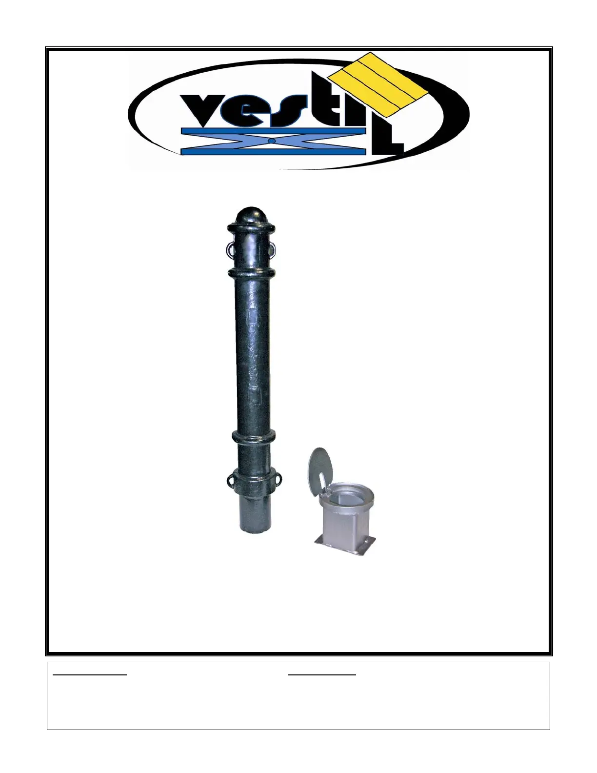
BOL-OR-40-BK SERIES BOLLARDS INSTALLATION INSTRUCTIONS
VESTIL MANUFACTURING CORP.
2999 NORTH WAYNE STREET, P.O. BOX 507, ANGOLA, IN 46703
TELEPHONE: (260) 665-7586 -OR- TOLL FREE (800) 348-0868
FAX: (260) 665-1339
URL: WWW.VESTILMFG.COM EMAIL: SALES@VESTIL.COM
Table of Contents Table of Figures
Product Introduction……………………. 2 Fig. 1 Determine depth of bollard socket………………………………… 2
Safety Recommendations…………....... 2 Fig. 2 Install drain tube…………………………………………………….. 2
Installation instructions……………...….. 2 - 3 Fig. 3 Place socket in the hole …………………………………………… 3
Fig. 4 Fill the hole with concrete …………………………………………. 3
Fig. 5 Install bollard ………………………………………………………… 3

Page
2 of 4
PRODUCT INTRODUCTION
Thank you fo r purchasing an Ornamental Steel Bollard (“bollard”). As the na me indicates, th ese bollards are
designed to serve a s ornamentation ONLY. Each b ollard conforms to ge neralized specifications disclosed in this
manual, an d fulfills ou r demanding standards for q uality, safety and d urability. Although t he steps required t o
install the product are relatively intuitive, all pe rsons who might participate in the installation of this bollard should
apply these instructions.
Specifications for BOL-OR-40-BK model bollards appear in the table below:
Model Socket Mounting
Usable Height in
Inches (cm)
Bollard Diameter in
Inches (cm)
Net Weight in
Pounds (kg)
BOL-OR-40-BK
Underground
40in.
(~101.6cm)
4½ in.
(~11.4cm)
84
(~38.2kg)
SAFETY RECOMMENDATIONS
Failure to read and understand the instructions included in this manual before installing the bollard
constitutes misuse of the product. If que stions remain after yo u finish reading this m anual, conta ct Vestil fo r
answers. DO NOT attem pt to re solve any problems with the bollard unless you are certain
that it will be safe to
use afterwards.
DO NOT contact live electrical wires, buried cables, underground gas lines, etc. during
installation. Determine the locations of all underground utility lines BEFORE beginning to dig the hole for
the bollard sleeve. Choose a location that is at least 3 feet away from all underground lines on all sides.
Installing the bollard safely is the responsibility of the end-user!
DO NOT attempt to install the bollard if you cannot comfortably lift it. Determine the net weight of the bollard
from the table on p. 3.
DO NOT modify the bollard or bollard sleeve without the express, written approval of Vestil.
Unauthorized modifications could render the device unsafe to use. Additionally, unauthorized
modification(s) automatically voids the warranty.
INSTALLATION INSTRUCTIONS:
STEP 1 Determine gro und level: Measure the b ollard
socket from the top to the bottom to determi ne the
necessary depth of the hole. (See FIG. 1 at right).
Step 2 Dig a hole for the below g round portio n
: Di g a
10in. x 10in. x 10in. hole (~25½ cm x 25½ cm x 25½ cm)
to contain the concrete and gr avel that will fix the bollard
socket in position.
Step 3 Partially fill hole and set bollard
: Fill the bottom of
the hole with approximately 4in. of gravel.
Step 4 Install drain tube
: Press a short length (app rox.
2in.) of ½in. (inner diameter) PVC pipe through the hole
in the bottom of the bollard socket.
Step 5 Place the socket i n the hole
: Set the s ocket in the
hole with th e PVC pipe extending i nto the grav el. The
bottom of the socket should rest on top of the gravel. (See
FIG. 3)
Step 6 Fill the rem ainder of the hole with concrete
: Pour
3,000psi compression rated co ncrete into the hol e, until
the surface of the concrete should be just belo w the top of
the so cket. Check the levelne ss of the socket and adjust
the po sition of the socket if ne cessary t o ma ke s ure t he
socket is level. It might be necessary to brace the so cket
to ensure that it does not shift as the concrete cures.
FIG. 1: Determine depth of bollard socket
FIG. 2: Install drain tube
FIG. 3: Place socket in the hole
6½ in.
(~16 ½ cm)
½ in. PVC drain tube
Ground
Gravel
Bollard socket
Bollard socket
Produktspecifikationer
Varumärke: | Vestil |
Kategori: | ej kategoriserat |
Modell: | BOL-OR-40-BK |
Behöver du hjälp?
Om du behöver hjälp med Vestil BOL-OR-40-BK ställ en fråga nedan och andra användare kommer att svara dig
ej kategoriserat Vestil Manualer
2 Oktober 2025
2 Oktober 2025
2 Oktober 2025
2 Oktober 2025
2 Oktober 2025
2 Oktober 2025
23 September 2025
22 September 2025
22 September 2025
22 September 2025
ej kategoriserat Manualer
- Tronic
- Bolt
- Digital Watchdog
- Mesko
- Pyle
- TAMA
- Practixx
- Hubelino
- Moser
- Mount-It!
- Access Lighting
- EBERLE
- Supermicro
- Speed-Link
- Watson
Nyaste ej kategoriserat Manualer
6 Oktober 2025
6 Oktober 2025
6 Oktober 2025
6 Oktober 2025
6 Oktober 2025
6 Oktober 2025
6 Oktober 2025
6 Oktober 2025
6 Oktober 2025
6 Oktober 2025