Whistler TRX-1 Bruksanvisning
Läs gratis den bruksanvisning för Whistler TRX-1 (76 sidor) i kategorin Radio. Guiden har ansetts hjälpsam av 35 personer och har ett genomsnittsbetyg på 4.9 stjärnor baserat på 2 recensioner. Har du en fråga om Whistler TRX-1 eller vill du ställa frågor till andra användare av produkten? Ställ en fråga
Sida 1/76
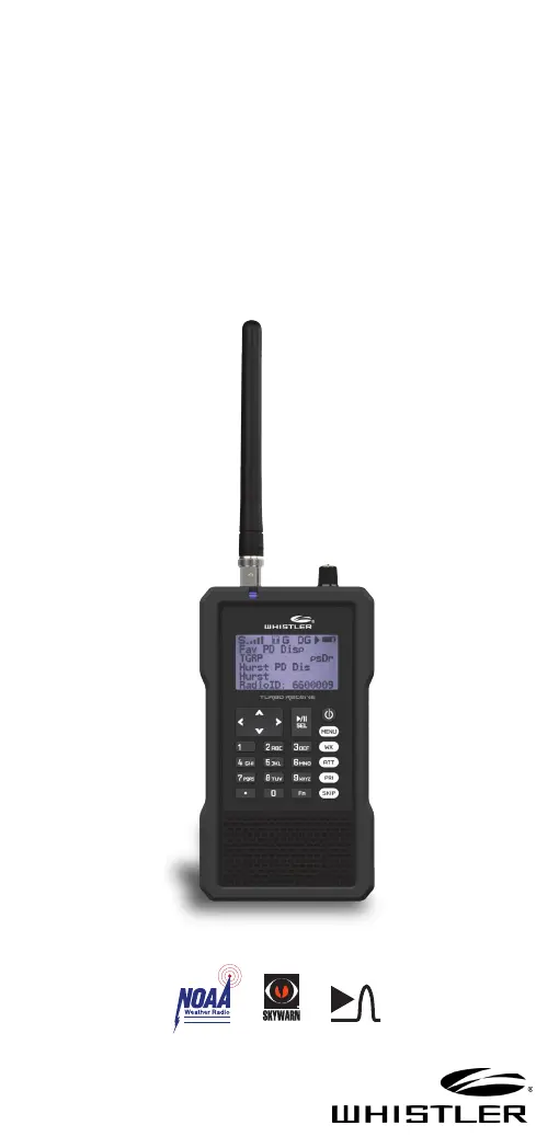
TRX-1
User Guide
All Hazards
NOAA’s National Weather Service
®
EZ SCAN DIGITAL
HANDHELD
RADIO
SCANNER
Produktspecifikationer
| Varumärke: | Whistler |
| Kategori: | Radio |
| Modell: | TRX-1 |
Behöver du hjälp?
Om du behöver hjälp med Whistler TRX-1 ställ en fråga nedan och andra användare kommer att svara dig
Radio Whistler Manualer

2 September 2024
2 September 2024
2 September 2024
Radio Manualer
Nyaste Radio Manualer
30 Mars 2026
28 Mars 2026
22 Mars 2026
19 Mars 2026
16 Mars 2026
16 Mars 2026
12 Mars 2026
12 Mars 2026
11 Mars 2026
5 Mars 2026