ADDAC System ADDAC511 Bruksanvisning
ADDAC System
ej kategoriserat
ADDAC511
Läs gratis den bruksanvisning för ADDAC System ADDAC511 (65 sidor) i kategorin ej kategoriserat. Guiden har ansetts hjälpsam av 14 personer och har ett genomsnittsbetyg på 5.0 stjärnor baserat på 7.5 recensioner. Har du en fråga om ADDAC System ADDAC511 eller vill du ställa frågor till andra användare av produkten? Ställ en fråga
Sida 1/65
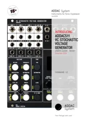
December.2024
USER’S GUIDE . REV01
FIRMWARE 1.0
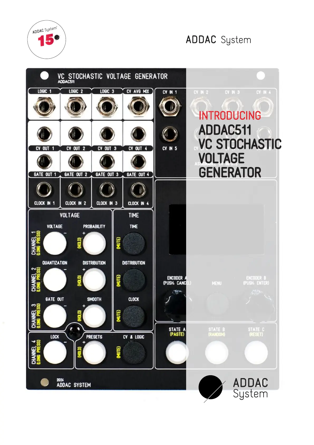
ADDAC511
VC STOCHASTIC
VOLTAGE
GENERATOR
INTRODUCING
From Portugal with Love!
Instruments for Sonic Expression
Est.2009
15
15th Year Anniversary
12.2009-12.2024
Produktspecifikationer
| Varumärke: | ADDAC System |
| Kategori: | ej kategoriserat |
| Modell: | ADDAC511 |
Behöver du hjälp?
Om du behöver hjälp med ADDAC System ADDAC511 ställ en fråga nedan och andra användare kommer att svara dig
ej kategoriserat ADDAC System Manualer
6 Oktober 2025
4 Augusti 2025
4 Augusti 2025
4 Augusti 2025
12 Juni 2025
ej kategoriserat Manualer
- Energizer
- RCA
- Kluge
- XP
- GoPro
- Outwell
- D-Link
- Apantac
- Uniprodo
- QNAP
- Ninja
- Dyson
- Ledlenser
- Imperial
- Strymon
Nyaste ej kategoriserat Manualer
23 Oktober 2025
23 Oktober 2025
23 Oktober 2025
23 Oktober 2025
23 Oktober 2025

23 Oktober 2025
23 Oktober 2025
23 Oktober 2025
23 Oktober 2025
23 Oktober 2025