Axiom A08C Bruksanvisning
Axiom Cykeldator A08C
Läs gratis den bruksanvisning för Axiom A08C (2 sidor) i kategorin Cykeldator. Guiden har ansetts hjälpsam av 28 personer och har ett genomsnittsbetyg på 4.5 stjärnor baserat på 5 recensioner. Har du en fråga om Axiom A08C eller vill du ställa frågor till andra användare av produkten? Ställ en fråga
Sida 1/2
Thank you for your purchase of the Axiom
®
A08C cyclocomputer. With all the features that a professional
rider needs to keep track of a ride, the A08C is the perfect training tool for any cyclist.
BATTERY INSTALLATION
To prolong battery life, the A08C battery is not installed at the factory. Before programming or using the computer the batterymust be
installed. The Axiom
®
A08C uses a common 3V CR2032 button cell battery (included). Replacement batteries are available at most camera and
electronic shops. Under normal usage a battery should last approximately one year. Note: Most problems that occur with cyclocomputers are
caused by dead or weak batteries. If you are having problems with your computer’s operation, check and replace the battery first.
STEP 1
Remove the battery cap from the bottom of the computer using a small coin. See Figure 1.
STEP 2
Install the battery in the battery compartment with the positive (+) side facing the battery cap. Be careful when installing the battery not to
damage the battery contact.
STEP 3
Reinstall the battery cap and tighten firmly, making sure the rubber O-ring does not get pinched or distorted, as this will compromise
the unit’s watertight seal.
Note:During a battery change your computer will retain programmed settings and odometer mileage for approximately 30 seconds. If the
battery is not replaced within 30 seconds, all data and programmed settings will be lost. Make a note of your current wheel size setting and
cumulative odometer mileage before replacing the battery so you can reprogram these values if necessary after the battery change (see
“Programming Wheel Size” and “Setting the Odometer”).
STEP 4
If for some reason the screen is blank or shows an irregular display after a battery change, press the “AC” button on the underside of the
computer head (see ”Reset Display Screens”).
BUTTONFUNCTION
LEFT BUTTON
Press and hold in the AVS, MXS, ATM(or TM) and DSTscreens to reset these display screens.
Press to start and stop the stopwatch (TM).
RIGHT BUTTON
Press to scroll through the AVS, MXS, ATM(or TM), DST, Cand ODOdisplay screens.
Press and hold in any screen to display the clock (CLK).
COMPUTERFUNCTIONS
WHEEL SIZE SETTING ((1)) or ((2)) (Figure 2)
Wheel circumference is used to calculate speed and distance. Setting range is 0000mm-2999mm.
To calculate and program wheel size, see “Determining Wheel Size”and “Programming Wheel Size.”
To select wheel size setting ((1)) or ((2)), advance to the MXSscreen and press and hold BOTH buttons for 3 seconds.
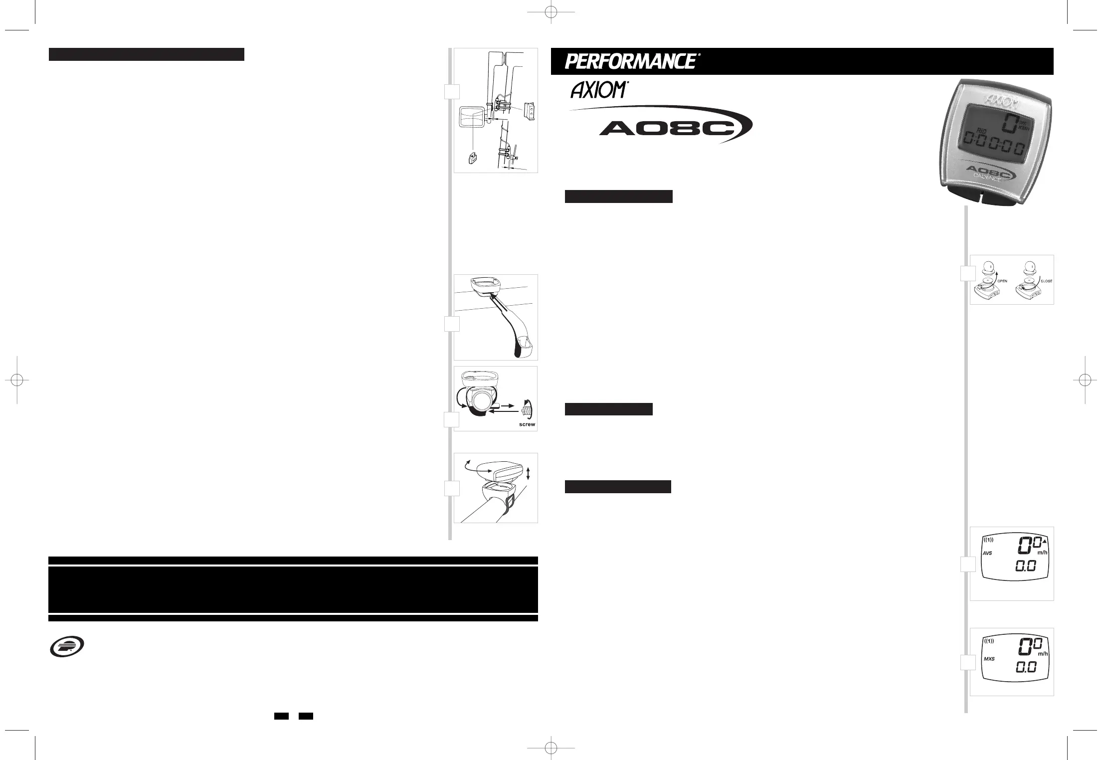
SPEEDOMETER (m/h or km/h) (Figure 2)
Displays instantaneous speed, up to 199.5 m/h or km/h.
Accurate to 0.5 mile or kilometer increments. Always displayed at the top of the screen.
To select m/h or km/h, see “Programming the Computer.”
SPEED COMPARISON(▼▲)(Figure 2)
Compares current speed to average speed. As you ride, a (▲) or (▼) will appear in the upper right corner of the display to indicate whether your
current speed is above (▲) or below (▼) your average speed. This function is automatic, requires no programming and cannot be disabled.
AVERAGE SPEED (AVS) (Figure 2)
Displays average speed up to 199.9 m/h or km/h. Calculated using true ride time (ATM)and trip distance (DST).
To reset AVSto zero, advance to the AVSscreen and press and hold the LEFT button for 3 seconds.
Note:MXS, ATM (or TM)and DSTwill also be reset to zero.
MAXIMUM SPEED(MXS) (Figure 3)
Displays the fastest speed attained during a ride, up to 199.5 m/h or km/h.
To reset MXSto zero, advance to the MXSscreen and press and hold the LEFT button for 3 seconds. Only MXSwill be reset to zero.
MAGNET, SENSOR & BRACKET INSTALLATION
WHEEL MAGNET AND SENSOR INSTALLATION
We recommend that you install your Axiom
®
A08C in the following manner, starting with the sensor units on the chainstay and working up to
the mounting bracket on the handlebar.
STEP 1
Identify the two sensors and magnets. The speed sensor is attached to the black cable and the cadence sensor is attached to thegray cable.
The cadence magnet is the square, flat magnet with “Cadence Magnet” printed on one side.
STEP 2
Using one of the included rubber shims and two of the zip-ties, mount the cadence sensor loosely (so that you can slide it around) to the out-
side of the left (non-drive side) chainstay. See Figure 15.
STEP 3
Use a zip-tie to attach the cadence magnet loosely to the inside of the left crank arm directly opposite the cadence sensor. The printing on
the magnet should face the sensor. Adjust the position of the magnet and sensor until the magnet passes the alignment mark on the sensor
with 1mm-3mm of clearance.
STEP 4
Using the second included rubber shim and two more zip-ties, mount the speed sensor loosely (so that you can slide it around) to the inside
of the left (non-drive side) chainstay. See Figure 15.
STEP 5
Attach the wheel magnet loosely to one of the spokes on the left side of the wheel directly opposite the speed sensor. Adjust the position of
the magnet and sensor until the magnet passes the alignment mark on the sensor with 1mm-3mm of clearance.
Note: 1mm is about the thickness of a penny. If the magnet and sensor are not close enough, the computer will not pick up a reading, or
readings will be inconsistent and erratic. Most problems encountered during installation of a new computer are related to magnet and sensor
alignment and spacing.
STEP 6
Once the speed and cadence sensors and magnets are aligned properly, tighten the zip-ties to secure all four in place.
STEP 7
Route the sensor cable along the frame toward the handlebar, and secure it with zip-ties or electrical tape to ensure it does not contact or
interfere with the crank or wheels in any way.
STEP 8
Carefully wrap the excess sensor cable around the front brake cable housing, leaving enough slack in the cable to allow for themovement of
the handlebar while steering. When finished, enough cable slack should remain for the computer mounting bracket to reach the handlebar.
Check to make sure all excess sensor cable is either taped down or wrapped around the brake cable housing so that nothing can snag it dur-
ing a ride.
BRACKET INSTALLATION
Use the included band clamp and a small screwdriver to attach the bracket to the handlebar as shown in Figure 16A & 16B. Once the
bracket is securely installed, trim the excess band with scissors.
HEAD UNIT INSTALLATION
Set the computer head into the bracket, and twist the head clockwise until you hear an audible “CLICK”, indicating that the unit is locked
firmly in place. See Figure 17.To remove the head unit, twist the head counterclockwise and then lift it out of the bracket.
TEST OF INSTALLATION
Once the installation procedure is complete, test the unit to make sure everything is adjusted and working properly.
STEP 1
Install the computer head in the handlebar bracket and use the RIGHT button to advance to the cadence (C)display screen.
STEP 2
Lift the rear of the bicycle and turn the cranks. The computer should register a speed reading and cadence reading within 1-2 seconds. If it
does not, check the alignment of the speed and cadence magnets with the sensors. Make sure the space between the magnets and sensors
is 3mm or less. Adjust as necessary and re-test.
Cyclocomputer
CADENCE
40-1880 1203_2
Performance Tech Support 1(800)553-8324
9am-6pm EST Monday-Friday
Performance, Inc.
One Performance Way
Chapel Hill, N.C. 27514
Made in Hong Kong
www.performancebike.com
PERFORMANCE and the Flying P Logo are registered marks of Performance, Inc.
c
25
c
25
1
c
c
2
Speedometer, Speed
Comparison & Average Speed
c
c
3
Maximum Speed
15
1-3 mm
1-3 mm
c
c
16A
c
c
16B
LOCK
UNLOCK
c
c
17
4
03_AxiomA08C_INS.qk 12/12/03 10:28 AM Page 1
Produktspecifikationer
| Varumärke: | Axiom |
| Kategori: | Cykeldator |
| Modell: | A08C |
Behöver du hjälp?
Om du behöver hjälp med Axiom A08C ställ en fråga nedan och andra användare kommer att svara dig
Cykeldator Axiom Manualer

11 Oktober 2025
20 September 2024
12 September 2024
Cykeldator Manualer
Nyaste Cykeldator Manualer
22 Mars 2026
14 Mars 2026
14 Mars 2026
10 Oktober 2025
10 Oktober 2025
10 Oktober 2025
9 Oktober 2025
26 September 2025
20 September 2025
10 September 2025