Busch-Jaeger 2CKA006220A0025 Bruksanvisning
Busch-Jaeger Smarth hem 2CKA006220A0025
Läs gratis den bruksanvisning för Busch-Jaeger 2CKA006220A0025 (4 sidor) i kategorin Smarth hem. Guiden har ansetts hjälpsam av 18 personer och har ett genomsnittsbetyg på 4.4 stjärnor baserat på 5 recensioner. Har du en fråga om Busch-Jaeger 2CKA006220A0025 eller vill du ställa frågor till andra användare av produkten? Ställ en fråga
Sida 1/4
2CDG941147P0003 / 10.03.2016
HA-M-0.6.1
6254/0.6
Busch/ABB-free@home
®
Deutsch
Heizungsaktor 6-fach, REG
WARNUNG
Bei direktem oder indirektem Kontakt mit spannungs-
führenden Teilen kommt es zu einer gefährlichen
Körperdurchströmung. Elektrischer Schock, Verbren-
nungen oder der Tod können die Folge sein.
ØVor Montage /Demontage Netzspannung freischalten!
Ø Arbeiten am 230 V-Netz nur von Fachpersonal
ausführen lassen.
nMontageanleitung sorgfältig lesen und aufbewahren.
n Weitere Benutzerinformationen unter www.abb.com/freeathome
oder durch Scannen des QR-Codes.
n Informationen zur Systemeinbindung siehe Systemhandbuch
(www.abb.com/freeathome).
Bestimmungsgemäßer Gebrauch
Das Gerät dient zum Ansteuern von 24 V ... 230 V thermoelektri-
schen Stellantrieben in Heiz- oder Kühlsystemen.
n Ausführliche Informationen zum Funktionsumfang siehe Tech-
nisches Handbuch (siehe QR-Code)
Technische Daten
Stromversorgung21 ... 30 V DC
Verlustleistung PMax. 2,0 W
BusanschlussBusanschlussklemme, schraubenlos
Nennspannung24 ... 230 V AC, 50/60 Hz
Nennstrom je Ausgang160 mA bei T
u
= 45 C°
Einschaltstrom je
Ausgangmax. 750 mA bei T
u
= 60 C°
Anschlussklemme
Ausgang
Kombikopf-Schraubklemmen (PZ 1)
0,2 ... 4 mm² feindrahtig
0,2 ... 6 mm² eindrahtig
SchutzartIP 20 nach EN 60 529
SchutzklasseII nach EN 61 140
Überspannungskategorie
III nach EN 60 664-1
Verschmutzungsgrad2 nach EN 60 664-1
LuftdruckAtmosphäre bis 2.000 m
Umgebungstemperatur- 5 °C – + 45 °C
Lagertemperatur- 20 °C – + 70 °C
Montage
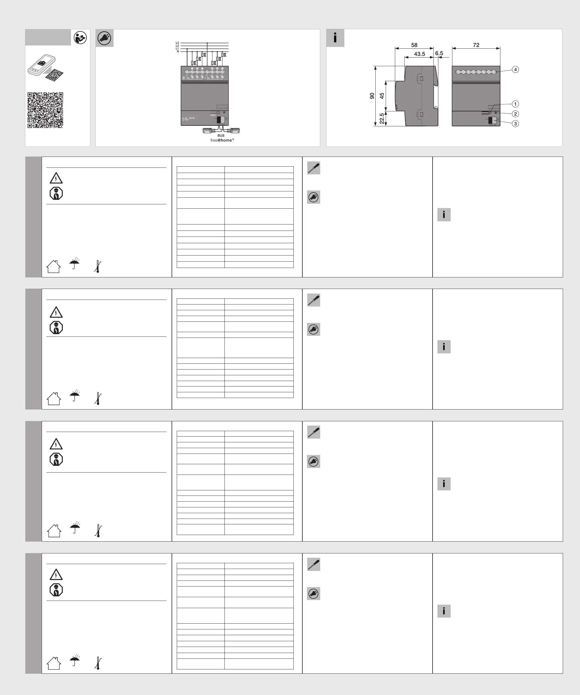
Das Gerät nur auf Hutschienen nach DIN EN 60715 installieren.
Klebeschild abziehen und in Liste einkleben (bei System Access
Point).
Anschluss
n Der elektrische Anschluss erfolgt über Schraubklemmen.
Die Klemmenbezeichnungen benden sich auf dem Gehäuse.
n Die Verbindung zur Buslinie erfolgt über die mitgelieferte Bus-
anschlussklemme (rot/schwarz).
n Jeweils 3 Ausgänge (A-C, D-F) sind gemeinsam abgesichert
und werden über eine Phase versorgt.
n Es können mehrere thermoelektrische Stellantriebe parallel an
einen Ausgang angeschlossen werden. Beim Parallelschalten
mehrerer Stellantriebe ist zu beachten, dass der maximale
Einschaltstrom bzw. Nennstrom nicht überschritten werden darf.
nTechnische Daten des Stellantriebs beachten!
Inbetriebnahme
Das an die Buslinie angeschlossene Gerät wird nach einigen Se-
kunden automatisch vom System erkannt. Die Geräte müssen zur
Ausführung der Funktionen parametriert werden.
n Ausführliche Informationen zu Inbetriebnahme und Parame-
trierung benden sich im Technischen Handbuch und in der
Onlinehilfe des „System Access Point“
(www.abb.com/freeathome).
nFirmware-Update erfolgt über System Access Point.
Bedienung
1 = Geräteidentikation während der Inbetriebnahme
2 = Identikations-LED 3 = Busanschlussklemme
4 = Anschlussklemmen
Service
ABB STOTZ-KONTAKT GmbH
Eppelheimer Straße 82, 69123 Heidelberg
Tel. DE 0800 3733 28 4
Tel. CH +41 58 586 07 00
E-Mail: [email protected]
www.abb.com/freeathome
English
Heating actuator 6gang, MDRC
WARNING
Dangerous currents ow through the body when com-
ing into direct or indirect contact with live components.
This can result in electric shock, burns or even death.
Ø Disconnect the mains power supply prior to installation/
disassembly!
Ø Permit work on the 230 V supply system to be
performed only by specialist staff.
n Please read the mounting instructions carefully and keep them
for future use.
n Additional user information is available at
www.abb.com/freeathome or by scanning the QR code.
n For information on system integration please see the system
manual (www.abb.com/freeathome).
Intended use
The device serves for activating 24 V ... 230 V thermoelectric actu-
ating drives in heating or cooling systems.
n For detailed information about the range of functions see the
technical reference manual (see QR code).
Technical data
Power supply21 ... 30 V DC
Power loss PMax. 2.0 W
Bus connectionBus connecting terminal, screwless
Nominal voltage24 ... 230 V AC, 50/60 Hz
Nominal current per
output
160 mA at T
u
= 45C°
Inrush current per outputMax. 750 mA at T
u
= 60C°
Connecting terminal
Output
Combi-head screw-type terminal
(PZ 1)
0.2 ... 4 mm² ne-wire
0.2 ... 6 mm² single-wire
Protection IP 20 according to EN 60 529
Protection class II according to EN 61 140
Overvoltage category III according to EN 60 664-1
Pollution degree 2 according to EN 60 664-1
Atmospheric pressureAtmosphere up to 2,000 m
Ambient temperature-5 °C – +45 °C
Storage temperature-20 °C – +70 °C
Mounting
Install the device only on mounting rails according to
DIN EN 60715. Remove the stick-on label and glue it into the list
(at System Access Point).
Connection
n The electrical connection is made via screw terminals.
The description of the terminals is found on the housing.
n The connection to the bus line is made via the enclosed bus
connection terminal (red/black).
n Three outputs (A-C, D-F) each are protected together and are
supplied via one phase.
n Several thermoelectric actuating drives can be connected in
parallel to one output. When connecting several actuating
drives in parallel it should ensured that the maximum inrush
current or nominal current is not exceeded.
nThe technical data of the actuating drives must be observed!
Commissioning
The device connected to the busline is automatically recognized by
the system after a few seconds. The devices must be parameter-
ised for the use of the functions.
n Detailed information about commissioning and parameteriza-
tion is available in the technical reference manual and the
online help of the "System Access Point"
(www.abb.com/freeathome).
nFirmware update is carried out via the System Access Point.
Operation
1 = Device identication during commissioning
2 = Identications-LED 3 = Bus connection terminal
4 = Connecting terminals
Service
ABB STOTZ-KONTAKT GmbH
Eppelheimer Straße 82, 69123 Heidelberg, Germany
Tel. +49 2351 956-1600
E-mail: [email protected]
www.abb.com/freeathome
Español
Actuador de calefacción 6 elementos, REG
ADVERTENCIA
En caso de entrar en contacto, directa o indirectamente, con
componentes por los que circule una corriente eléctrica, se
puede sufrir una descarga eléctrica peligrosa, cuyo resultado
puede ser choque eléctrico, quemaduras o, incluso, la muerte.
Ø¡Desconecte la tensión de red antes de proceder al mon
-
taje o desmontaje!
Ø Encargue los trabajos en la red eléctrica de 230 V solo al
personal técnico competente.
n
Lea detenidamente y guarde en lugar seguro el manual de montaje.
n
Más información para usuarios en www.abb.com/freeathome o esca-
neando el código QR.
n
Para más información sobre la integración en el sistema, consulte el
manual del sistema (www.abb.com/freeathome).
Uso conforme al n previsto
El aparato sirve para controlar accionamientos termoeléctricos reguladores
de 24 ... 230 V con sistemas de calor o frío.
n
Si desea información más detallada sobre las funciones, consulte el
manual técnico (véase el código QR).
Datos técnicos
Alimentación de corriente
21 ... 30 V c.c.
Potencia disipada PMáx. 2,0 W
Conexión de bus
Borne de conexión de bus, sin tornillo
Tensión nominal24 ... 230 V c.a., 50/60 Hz
Corriente nominal por
salida
160 mA con T
ent
= 45 °C
Corriente de conexión
por salidamáx. 750 mA con T
ent
= 60 °C
Borne de conexión
Salida
Bornes roscados de cabeza combi (PZ 1)
0,2 ... 4 mm² exible
0,2 ... 6 mm² de un hilo
Tipo de protecciónIP 20 según EN 60 529
Clase de protecciónII según EN 61 140
Categoría de sobretensión
III según EN 60 664-1
Grado de contaminación2 según EN 60 664-1
Presión del aireAtmósfera hasta 2 000 m
Temperatura ambiente-5 °C – +45 °C
Temperatura
de almacenamiento
-20 °C – +70 °C
Montaje
Instale el aparato sobre carriles DIN según la norma EN 60715.
Retire la etiqueta adhesiva y péguela en la lista (en System Access
Point).
Conexión
n La conexión eléctrica se realiza mediante bornes roscados.
Las denominaciones de los bornes se encuentran en la carca-
sa.
n La conexión con la línea de bus se efectúa con el borne de
conexión de bus suministrado (rojo/negro).
n Cada 3 salidas (A-C, D-F) cuentan con una protección común
y son alimentadas por una fase.
n Se pueden conectar varios accionamientos termoeléctricos
reguladores en paralelo a una misma salida. Al conectar en
paralelo varios accionamientos reguladores, se debe tener
en cuenta que no se debe superar la corriente de conexión o
corriente nominal máximas.
n¡Obsérvense los datos técnicos del accionamiento regulador"
Puesta en servicio
El sistema reconoce automáticamente tras unos segundos el
aparato que se conecta a la línea de bus. Para la ejecución de las
funciones adicionales es necesario parametrizar los aparatos.
n Podrá encontrar información detallada sobre la puesta en
servicio y sobre la parametrización en el manual técnico y en
la ayuda online del “System Access Point” o punto de acceso
del sistema (www.abb.com/freeathome).
n La actualización del rmware se realiza a través del System
Access Point (punto de acceso del sistema).
Manejo
1 = Identicación de los aparatos durante la puesta en servicio
2 = LED de identicación 3 = Borne de conexión de bus
4 = Borne de conexión
Servicio postventa
ABB STOTZ-KONTAKT GmbH
Eppelheimer Straße 82, 69123 Heidelberg
Tel. +34 902 11 15 11
E-Mail: [email protected]
www.abb.com/freeathome
Italiano
Attuatore riscaldamento 6x, REG
AVVERTIMENTO
Il contatto diretto o indiretto con parti attraversate da corrente
elettrica provoca pericolosi ussi di corrente attraverso il corpo.
Le conseguenze possono essere folgorazione, ustioni o morte.
ØPrima del montaggio o dello smontaggio scollegare la
tensione di rete!
Ø Afdare gli interventi sulla rete elettrica a 230 V esclusiva
-
mente a personale specializzato.
nLeggere e conservare con cura le istruzioni per il montaggio.
n Maggiori informazioni per l'utente disponibili sul sito
www.abb.com/freeathome o tramite scansione del codice QR.
n Per informazioni sull'integrazione nel sistema vedere il manua-
le del sistema (www.abb.com/freeathome).
Uso conforme alle prescrizioni
L'apparecchio è stato progettato per l'attivazione di attuatori
termoelettrici a 24 V ... 230 V installati in sistemi di riscaldamento o
raffreddamento.
n Per informazioni dettagliate sulle funzioni disponibili consultare
il manuale tecnico (vedere il codice QR).
Dati tecnici
Alimentazione elettrica21 ... 30 V DC
Potenza dissipata PMassimo 2,0 W
Collegamento bus
Morsetto di allacciamento bus, senza viti
Tensione nominale24 ... 230 V AC, 50/60 Hz
Tensione nominale per
ogni uscita
160 mA con T
u
= 45 C°
Corrente di inserzione
per ogni uscitamax 750 mA con T
u
= 60 C°
Morsetto
Uscita
Morsetti a vite con testa a intaglio (PZ 1)
0,2 ... 4 mm² a lo ne
0,2 ... 6 mm² monolo
Tipo di protezioneIP 20 a norma EN 60 529
Classe di protezioneII A norma EN 61 140
Categoria di sovratensionesione
III a norma EN 60 664-1
Grado di sporcizia2 a norma EN 60 664-1
Pressione ariaAtmosfera no a 2.000 m
Temperatura ambiente- 5 °C – + 45 °C
Temperatura
di immagazzinamento
- 20 °C – + 70 °C
Montaggio
Installare l'apparecchio esclusivamente su guide DIN conformi a
DIN EN 60715. Staccare l'etichetta adesiva e incollarla nella lista
(per System Access Point).
Collegamento
n Il collegamento elettrico è realizzato tramite morsetti a vite. I
codici dei morsetti sono riportati sulla scatola.
n Il collegamento alla linea bus è realizzato tramite il morsetto
bus allegato (rosso/nero).
n Per ogni 3 uscite (A-C, D-F) è predisposta una protezione e
sono alimentate da una fase.
n Ad una uscita si possono collegare in parallelo più attuatori
termoelettrici. In caso di commutazione parallela di più attuatori
attenzione a non superare la corrente d'inserzione o la tensio-
ne nominale massima.
nOsservare le speciche tecniche dell'attuatore!
Messa in funzione
L'apparecchio collegato alla linea bus viene rilevato automaticamente
dal sistema dopo alcuni secondi. L'apparecchio collegato alla linea bus
viene rilevato automaticamente dal sistema dopo alcuni secondi. Per
utilizzare le funzioni è necessario parametrizzare gli apparecchi.
n Per informazioni dettagliate sulla messa in servizio e sulla para-
metrizzazione consultare il manuale tecnico o la guida online del
"System Access Point" (www.abb.com/freeathome).
n L'aggiornamento rmware avviene tramite System Access Point.
Uso
1 = identicazione dell'apparecchio durante la messa in servizio
2 = LED identicativo 3 = Morsetto di allacciamento bus
4 = Morsetti
Service
ABB STOTZ-KONTAKT GmbH
Eppelheimer Straße 82, D-69123 Heidelberg
Tel. IT 0800 55 1166
Tel. CH +41 58 586 07 00
E-Mail: [email protected]
www.abb.com/freeathome
www.abb.com/freeathome
www.busch-jaeger.de/freeathome
IP20
-5 °C
+45 °C
IP20
-5 °C
+45 °C
IP20
-5 °C
+45 °C
IP20
-5 °C
+45 °C
Produktspecifikationer
| Varumärke: | Busch-Jaeger |
| Kategori: | Smarth hem |
| Modell: | 2CKA006220A0025 |
| Produkttyp: | Termostatställdon |
| Inbyggd display: | Nej |
| Bredd: | 72 mm |
| Djup: | 64 mm |
| Höjd: | 90 mm |
| LED-indikatorer: | Ja |
| Certifiering: | RoHS, CE |
| Kompatibla produkter: | Busch-free@home |
| Antal kanaler: | 6 kanaler |
| Spänning: | 24 V |
| Antal utgångskanaler: | 6 |
| Produktens färg: | Blue, Grey |
| Temperatur vid drift: | -5 - 45 ° C |
| Internationellt skydd (IP) kod: | IP20 |
| Ström: | 0.16 A |
| Antal stödda enheter: | 3 |
Behöver du hjälp?
Om du behöver hjälp med Busch-Jaeger 2CKA006220A0025 ställ en fråga nedan och andra användare kommer att svara dig
Smarth hem Busch-Jaeger Manualer

29 Mars 2025
29 Mars 2025
22 September 2024
22 September 2024
22 September 2024
22 September 2024
22 September 2024
22 September 2024
14 September 2024
13 September 2024
Smarth hem Manualer
Nyaste Smarth hem Manualer
29 Mars 2025
27 Mars 2025
18 Mars 2025
18 Mars 2025
12 Mars 2025
26 Februari 2025
19 Februari 2025
18 Februari 2025
16 Februari 2025
14 Februari 2025