Datapath VSN972 Bruksanvisning

Läs nedan 📖 manual på svenska för Datapath VSN972 (93 sidor) i kategorin Kontroller. Denna guide var användbar för 16 personer och betygsatt med 4.5 stjärnor i genomsnitt av 2 användare

Sida 1/93
WALL CONTROLLER
USER GUIDE
VSN972 and VSN1172
2nd Generation Wall Controllers
Version 1.0.0
Contents 2
Table of Contents
Disclaimer/Copyright Statement..................................................................................................5
UK Headquarters and Main Sales Oce........................................................................................5
Datapath North America................................................................................................................................................5
Datapath Japan..............................................................................................................................................................5
Quick Start Guide.......................................................................................................................6
Contents........................................................................................................................................................................6
Step 1 - Keyboard and Mouse.........................................................................................................................................6
Step 2 - Connect Expansion Chassis (Optional)...............................................................................................................7
Step 3 - Connect to a Network (Optional).......................................................................................................................7
Step 4 - Connect Input Source........................................................................................................................................8
Step 5 - Connect Control Screen (Optional) and Monitors...............................................................................................8
Step 6 - Powering up the System....................................................................................................................................9
Step 7 - Windows®10 Setup...........................................................................................................................................10
Step 8 - Display Setup Windows® 10..............................................................................................................................11
Step 9 - WallControl 10 (Optional)..................................................................................................................................12
Step 10 - Wall Control-red/SQX (Optional).....................................................................................................................15
Chapter 1 - Introduction.............................................................................................................16
1.1 Introduction............................................................................................................................................................16
1.2 Systems .................................................................................................................................................................16
1.3 How the User Guide is Organised............................................................................................................................16
1.4 Fonts and Symbols.................................................................................................................................................16
1.5 Terminology and Denitions...................................................................................................................................17
Chapter 2 - Safety.....................................................................................................................19
2.1 Safety Precautions.................................................................................................................................................19
2.2 Rack Mount Safety Instructions..............................................................................................................................20
2.3 Unpacking and Initial Inspection.............................................................................................................................20
Chapter 3 - General....................................................................................................................21
3.1 Overview.................................................................................................................................................................21
3.2 Systems in the VSN972 and VSN1172 Range............................................................................................................21
3.3 Associated Output/Input Cards and Related Products..............................................................................................22
Contents
Contents
3.4 Product Datasheets................................................................................................................................................22
Chapter 4 - Hardware.................................................................................................................23
4.1 VSN972 / VSN1172 Chassis.......................................................................................................................................23
4.2 SBC ‘s.....................................................................................................................................................................24
4.3 Backplanes..............................................................................................................................................................24
4.4 Backplane LED’s.....................................................................................................................................................25
Chapter 5 - Cabling....................................................................................................................27
5.1 Connecting the Keyboard and Mouse.....................................................................................................................27
5.2 Connecting an Expansion Chassis...........................................................................................................................27
5.3 Slots and Bandwidths - Optical Systems..................................................................................................................31
5.4 Connecting to a Network........................................................................................................................................33
5.5 Connecting Input Sources.......................................................................................................................................34
5.6 Connect Monitors and Control Screen.....................................................................................................................34
5.7 Connecting Power Cables........................................................................................................................................36
Chapter 6 - Operation................................................................................................................37
6.1 Switching On...........................................................................................................................................................37
6.3 Initial System Boot on Delivery...............................................................................................................................38
6.4 Opening Wall Control-red/Wall Control-SQX (Optional)..........................................................................................39
6.5 Displaying Video Captures.......................................................................................................................................40
6.6 Opening WallControl 10 (Optional)..........................................................................................................................41
Chapter 7 - Software..................................................................................................................43
7.1 Wall Control-red/SQX (Optional).............................................................................................................................43
7.2 WallControl 10 (Optional)........................................................................................................................................45
7.3 Wall Monitor (Optional)...........................................................................................................................................48
7.4 Vision Application (Optional)..................................................................................................................................50
7.5 Software Utilities.....................................................................................................................................................52
Chapter 8 - Troubleshooting .......................................................................................................53
8.1 Frequently Asked Questions (FAQs) Wall Control-red..............................................................................................53
8.2 Technical Support ..................................................................................................................................................55
3
Copyright Statement
Disclaimer/Copyright Statement
© Datapath Ltd, England 2017
Datapath Limited claims copyright on this User Guide. No part of this User Guide may be reproduced, released, disclosed,
stored in any electronic format, or used in whole or in part for any purpose other than stated herein without the express
permission of Datapath Limited.
Whilst every e฀ort is made to ensure that the information contained in this User Guide is correct, Datapath Limited make no
representations or warranties with respect to the contents thereof, and do not accept liability for any errors or omissions.
Datapath reserves the right to change speci฀cation without prior notice and cannot assume responsibility for the use made of
the information supplied. Datapath Limited acknowledges all registered trademarks used within this User Guide.
UK Headquarters and Main Sales O฀ce
Datapath Ltd.,
Bemrose House,
Bemrose Park,
Wayzgoose Drive
Derby, DE21 6, UK
Tel: +44 (0) 1332 294441
Fax: +44 (0) 1332 290667
Email: sales@datapath.co.uk
www.datapath.co.uk
Datapath North America
2550 Blvd of the Generals
Suite 30
Norristown, PA 19403
U.S.A
Tel: +1 484 679 1553
Email: sales@datapath.co.uk
www.datapath.co.uk
Datapath Japan
HULIC & New SHINBASHI 501,
2-11-10 Shimbashi
Minato-ku,Tokyo 105-0004
Japan
Tel: +81 (0)80 3475 7420
Email: sales@datapath.co.uk
www.datapath.co.uk
5
Quick Start Guide
Quick Start Guide
Main System
VSN Main chassis
Mouse/Keyboard
Recovery Media
Cables/Adapters
Accessories Pack
Chassis Key
MAC Address Labels
Expansion Unit
VSN Expansion chassis
(SLinkG3/SLink Optical Card Installed)
Accessories Pack
Chassis Key
HLink-G3/HLink Optical Card
ExCable-G3/ExCable Optical
Contents
A version of the Quick Start Guide is included below for your convenience.
Step 1 - Keyboard and Mouse
Note: VSN Expansion units may have been purchased as part of a large system or ordered separately.
Each Datapath system is custom built therefore the number and type of input and output cards will di฀er from system to
system.
Accompanying this Quick Start Guide are PCIe card product lea฀ets which give details on how the cards are installed and any
accessories supplied with them.
Connect Keyboard and Mouse to USB Ports.
6
Quick Start Guide
Quick Start Guide
Step 2 - Connect Expansion Chassis (Optional)
Connect the HLink-G3 card to the SLink-G3 card using the ExCable.
( )
ExCable-G3, packaged and shipped with the expansion unit.
Step 3 - Connect to a Network (Optional)
Network Cable not supplied.
7
Each Datapath system is custom built. The number and type of inputs will dier from system to system.
Contained within the documentation pack are PCIe card product leaets which give details on how the cards are connected.
Step 4 - Connect Input Source
Quick Start Guide
Quick Start Guide
3 x 2 Video Wall 4 x 2 Video Wall
Control Screen
Monitor 2
Monitor 3
Monitor 4
Monitor 5
Monitor 7
Monitor 6
Monitor 8
Monitor 1
Connect graphic outputs to
monitors using DisplayPort cables,
(not supplied).
Our VSN972/1172 wall controllers are congured to use a control screen prior to leaving the factory. Connect a control screen to
the SBC as shown above.
VGA/DVI
Step 5 - Connect Control Screen (Optional) and Monitors
8
Quick Start Guide
Quick Start Guide
Connect power cables then plug into a
mains supply.
Switch on the power supply units.
Switch on the system.
3
If you have a VSN Expansion Chassis connected to the main unit the power supply units on the expansion chassis should be
switched on prior to the main unit. There is no requirement to switch on the system (3) on an expansion chassis.
2
1
RPSU System ATX System
Step 6 - Powering up the System
1
2
2
1
3
9
Quick Start Guide
Quick Start Guide
Step 7 - Windows®10 Setup
Computer Name:
It is recommended that only Internet-standard characters are used in the computer name. The standard characters are the
numbers 0 through to 9, upper and lower-case letters from A through to Z and the hyphen character. Computer names cannot
consist entirely of numbers, contain spaces or use special characters such as: < > ; : “ ?* + = \ | ? ,.
There is no requirement for users to activate Windows 10, activation is done automatically.
®
Enter localisation details.
10
2
Quick Start Guide
Step 8 - Display Setup Windows® 10
Start | Control Panel | Display | Change Display Settings
1
3
Quick Start Guide
4
11
Quick Start Guide
Step 9 - WallControl 10 (Optional)
Quick Start Guide
Start | All Programs | WallControl 10 - Client
When WallControl 10 is opened for the ฀rst time it is strongly recommended that you read through the help ฀le prior to using
the application.
The WallControl 10 - User Interface
1
2
3 4 5
Start | All Programs | WallControl 10 - Server
Before opening the Client and Security Administration Client interfaces you will need to start the Server by clicking on it in the
Programs menu. Starting the Server loads both the WallControl 10 Server and the WallControl 10 Security Server. The
WallControl 10 Client will only detect servers that are running.
12
Quick Start Guide
Quick Start Guide
1 Indicates the server you are connected too.
2 A representation of the display wall(s) associated with the server.
3 Sources Tab - Displaying all the sources connected to the server for use on the display wall.
4 Layouts Tab - Used to save, recall and share display wall layout con฀gurations.
5 Templates Tab - Use templates to assist in the design of speci฀c display wall layouts.
When opened, the display wall tab shows a live representation of the physical wall and the sources available to display on it. To
place a source on the video wall, simply click on the required source in the sources tab and drag it onto the display wall
representation.
The application help ฀le contains videos explaining how multiple sources can be selected, how to use and create templates and
how to save, recall and share layout ฀les.
Display Wall
Tab
Sources
Click on the display wall representation to open the display wall tab.
Display Wall
Representation
13
Start | All Programs | WallControl 10 - Security Administration Client
Quick Start Guide
Quick Start Guide
The WallControl 10 - Security Administration Client (Only Available with Pro Version )
The WallControl 10 - Security Administration Client allows Administrators to assign speci฀c users to roles on a wall by wall basis.
For example, a User can be assigned a role allowing unrestricted access on one wall but assigned a role on another wall which
only allows the opening of pre-determined layouts.
Prior to the Security Client being used for the ฀rst time, the SecurityOnO฀.exe program must be run to enable security
protection for the application. To run the SecurityOnO฀.exe, ensure you are logged into Windows® with Administrator Rights.
Locate and double click on the SecurityOnO฀.exe ฀le:
Program Files (x86) \WallControl 10\ Security Server\SecurityOnO฀
A WallControl 10-Pro serial dongle must be inserted into a vacant USB port. If the dongle is removed or swapped, the Security
Client will not open and an error message is displayed, therefore it is important the dongle is not removed.
The WallControl 10 Security Application help ฀le contains information on how to:
Import users from the Windows® Active Directory into the database.
Create and edit roles.
Assign permissions to providers, layouts and sources giving speci฀c roles access to them.
Assign roles to walls.
14
Start | All Programs | Wall Control | Wall Control-My Computer
1 2 3 4
1 The Icons displayed in the application toolbar identify which type of source is available to each
input
2 Icons highlighted green indicate an active capture for that particular input.
3 Representation of the control screen if one is being used.
4 Representation of the video wall desktop.
Step 10 - Wall Control-red/SQX (Optional)
Quick Start Guide
To open a video window click and drag an active capture into the Wall Control application.
Use the Help Menu for a comprehensive guide on the features of the Wall Control application.
Quick Start Guide 15
Introduction
Chapter 1 - Introduction
1.1 Introduction
Congratulations on your purchase of the Datapath Wall Controller system. The wall controller has been manufactured and
tested to the highest standards oering unparalleled quality and reliability. The aim of this user guide is to assist you through
the installation of the system safely and eectively and act as a reference guide for future use. Do not switch on the system
until all the relevant cables have been connected.
1.2 Systems
The systems covered by this user guide are the VSN9x2 and the VSN11x2 video wall controllers and expansion chassis ranges.
1.3 How the User Guide is Organised
The user guide is broken down into chapters and each chapter into sections. Chapters, sections and pages are numbered
individually. Pages are numbered in Arabic numerals with the exception of the cover page (no numbering).
1.4 Fonts and Symbols
1.4.1 Fonts
The font used throughout the user guide is Corbel however the following font styles mean:
Bold = Used to describe menu titles, buttons in software or elements that you must type exactly as shown in the Command Line
Interface
Ellipsis (...) - Parameter that can be repeated several times in a command line.
Between brackets ([]) - Optional items.
Between braces ({}) - Set of choices (separated by I) from which you must choose only one.
Italic = Information that must be supplied by the user
Courier = Indicates code or program output.
Blue Underlined = Indicates a hyper-link. Some hyper-links may be linked to live websites.
1.4.2 Symbols
Symbols are used throughout this user guide to assist the user in quickly identifying important safety information and notes.
Yellow triangle indicates that failure to observe the instructions could result in injury
and/or damage to the system.
Lifting precautions should be considered.
White arrow in a blue box indicates a useful tip.
White exclamation mark in a blue box indicates important information.
16
Introduction
1.5 Terminology and Denitions
1.5.1 Backplane
Datapath manufactures types of backplanes; the Express9 Gen 3 (9 slots) and the Express11 Gen 3 (11 slots).
The Express 9 Gen 3 is used in the VSN972/990 and the VSN900X expansion chassis and the Express 11 Gen 3 is used in the
VSN1172/1192 and the VSN1100X expansion chassis.
The backplanes use advanced PCI Express switches to create a high bandwidth fabric that connects up to 9 or 11 PCI Express
plug in cards in a single system. This system can be expanded to create more PCI Express slots using the VSN900x/1100X
expansion units.
1.5.2 BIOS
Basic Input/Output System: Used during system boot up to initialise and test system hardware and load the operating system.
Each BIOS is specically designed to work with a particular motherboard.
1.5.3 Command Line Interface
Preferred means by advanced users of issuing commands and controlling an application or operating system. Programs with a
Command Line Interface are generally considered easier to automate via scripting.
1.5.4 Control Screen
Some systems are shipped with the BIOS congured to boot the system o the onboard graphics device. This output can then
be used as the Control Screen for a typical video wall. The content of the control screen is not displayed on the video wall desk-
top and can be used to host the Wall Control application window.
1.5.5 SBC
A Single Board Computer built on a single circuit board. SBC’s in the VSN972/1172 are plugged into the PICMG1.3 slot on the
Express9 and Express 11 backplanes
1.5.6 SDK
Software Development Kit: A set of software development tools which allows the creation of certain applications
1.5.7 WallControl 10 (Optional)
An optional software application for controlling and managing Vision, IP-Camera and third party application windows on a
Datapath Wall Controller. Providing a graphical representation of the video wall and a toolbar through which to manipulate all
available input sources and applications.
1.5.8 WallControl 10 Security Administration Client (Optional)
The WallControl 10 Security Administration Client allows Administrators to assign specic users to roles on a wall by wall basis.
The Security Administration Client is only available with WallControl 10-Pro.
1.5.9 Wall Monitor
A software application that enables the user to monitor the temperatures and voltages of system components.
Introduction 17
Safety
Chapter 2 - Safety
2.1 Safety Precautions
To prevent damage to your Datapath product or injury to personnel operating the equipment, please read the following safety
precautions prior to operation. These instructions should be made available to all those who will use and operate Datapath
products.
2.1.1 Power Supply
All Datapath products require a mains power supply. This power supply must be disconnected when equipment is being
upgraded or relocated.
2.1.2 Cables
Do not expose cables to any liquids; doing so may cause a short circuit which could damage the
equipment. Do not place heavy objects on top of any cables as this can cause damage and possibly lead to exposed live wires.
2.1.3 Ventilation
All computer equipment should be located in a well ventilated area. All ventilation holes on the computer casing must be kept
clear of any obstruction at all times. Failure to do so will result in the system over heating and damaging your equipment.
2.1.4 Working Environment
The equipment should be located in an environment free from dust, moisture and extreme changes in temperature and should
be placed on a stable and solid work surface. Liquids (hot/cold drinks etc) should not be placed near the equipment as spillage
could cause serious damage.
2.1.5 Gas/Flammable Liquids
Electronic equipment should never be used in the presence of gas or any ammable liquid, doing so could result in an explosion
or serious re.
2.1.6 Smoke/Unusual Smells
Should you notice smoke or unusual smells being emitted from your system, turn o and unplug the system from the mains
supply. The system should then be passed to a qualied technician for inspection. Continued operation could result in personal
injury and damage to property.
2.1.7 Maintenance
Apart from what is detailed in this user guide, maintenance should only be carried out by competent technicians, any Datapath
plug-in cards that are physically damaged should be returned to Datapath for repair using Datapath RMA procedures.
2.1.8 Replaceable Batteries
Caution: Risk of explosion if batteries are replaced by an incorrect type. Dispose of used batteries according to the local laws /
regulations and manufacturer’s instructions.
19
General
Chapter 3 - General
3.1 Overview
Datapath’s VSN972 and VSN1172 systems are powerful video wall controllers, capable of delivering Ultra High Denition video
across large, multi-screen display installations. For use in a host of environments, from CCTV security suites to sports stadia,
and from military installations to utility management centres. Fully compatible with Datapaths world leading portfolio of PCI
Express video capture and graphics cards that oer Ultra High Denition video for storage and display, including the ability to
capture HDCP sources without any display restrictions.
Each system has been designed for use in demanding control room environments. Each component has been subjected to
rigorous testing to ensure the highest levels of performance and reliability.
In summary:
High performance and reliability in demanding conditions
Suited for 24/7 applications
Can be operated via a network
PCIe switched fabrics enables systems to be expanded using additional expansion chassis
Wall Control software (optional) - Display video on the desktop in real time using an array of features
Wall Monitor software (optional) - Provides monitoring of the temperature and voltage sensors on system components
3.2 Systems in the VSN972 and VSN1172 Range
Features
Systems Express 9
Backplane
Express 11
Backplane SBC 5 SBC 6 SBC 7 Intel®
Core i7
Dual Intel®
Core Xeon
Single
Intel® Core
Xeon
RPSU ATX
VSN972 x x x x x *
VSN1172 x x x x
VSN900X x x x *
VSN1100X x x
* Available with either and RPSU or ATX power supply.
21
General
We are constantly updating our product portfolio, for the latest details on our full product range please visit our website:
www.datapath.co.uk
3.4 Product Datasheets
Product datasheets are available to download from www.datapath.co.uk
General
3.3 Associated Output/Input Cards and Related Products
The following table lists the range of Datapath products associated with the VSN972/1172 range of video wall controllers:
Product Description
ImageDP4+ Quad output DisplayPort graphics card.
ActiveSQX Dedicated IP Streaming decoding card.
VisionSC-DP2 Dual channel, 4K UHD DisplayPort capture card.
VisionSC-SDI4 Four channel 3G-SDI video capture card.
VisionSC-HD4+ Quad HDMI video capture card.
VisionAV-HD Four lane PCI Express capture card with 2 x HD DVI-I and 1 SD channels.
VisionAV-SDI Four lane PCI Express capture card with 1 x HD DVI-I, SD, SDI channels.
VisionHD4 Eight lane PCI Express capture card with four independent DVI-I HD channels.
VisionRGB-E1s Single channel HD video capture card.
VisionAV Single Channel HD and single channel SD video capture card.
VisionRGB-E2s Dual channel HD video capture card.
VisionDVI-DL Single channel Dual-Link video capture card.
VisionSD4+1s Video capture card with four channels of SD and one of HD.
VisionSDI2 Dual channel HD-SDI video capture card.
VisionSD8 Eight channel SD video capture card.
HLink-G3 Host link card for Gen.3 expansion systems.
SLink-G3 Slave link card for Gen.3 expansion systems.
ExCable-G3 Copper cable Gen.3 for expansion systems.
HLink-Optical Host link card for optical linked expansion system.
SLink-Optical Slave link card for optical linked expansion system.
ExCable-Optical Locking optical cable available in 50m and 100m lengths.
22
Hardware
Chapter 4 - Hardware
4.1 VSN972 / VSN1172 Chassis
4.1.1 Front
Front Panel
1 = Power, on-o 5= Reset Button
2= PSU Alarm Reset 6= USB Ports
3= Power LED 7= Removable Hard Drives
4= HDD LED
4.1.2 Rear
Rear Panel - RPSU
Rear Panel - ATX (VSN 972 only)
R1= Power Switch R3= Ethernet Ports
R2= USB Ports R4= DVI-I Output
1 32 4 5 6 7
R2
R1
R3
R4
R1 R2
R3
R4
23
Hardware
4.2 SBC ‘s
Datapath have developed, tested and qualied an SBC for use in the VSN972/1172 range of video wall controllers providing
improvements to the BIOS and a higher performance for Windows based software applications.
4.2.1 SBC6
The Portwell 8113-Q170:
An Intel® 7th Gen Kaby Lake Pentium Core i7.
Used in the VSN972 and the VSN1172.
4.3 Backplanes
The Datapath backplanes use advanced PCI Express switches to create a high bandwidth fabric for connecting multiple PCI
Express into a system.
4.3.1 Express9-G3
Nine slot PCI Express backplane - 8 x 4 lane slots, 1 x 8 lane slot and 1 x PICMG 1.3 slot.
Used in the VSN972 and the VSN900X.
Express9-G3
Hardware
4.3.2 Express11-G3
Eleven slot PCI Express backplane - 11 x 8 lane PCI Express slot and one PICMG 1.3 slot.
Used in the VSN1172 and VSN1100X.
24
Hardware
Hardware
Express11-G3
4.4 Backplane LED’s
Both the Express9-G3 and the Express11-G3 backplanes have a LED’s tted for each PCI Express slot and the PICMG1.3 slot.
The LED’s indicate the following:
LED1 ON = +5V standby voltage present
LED2 ON = +5V supply present
LED3 ON = +12V supply present
LED4 ON = +3.3V supply present
LED5 ON = PICMG link speed = Gen3, FLASH-FAST = Gen2, FLASH-SLOW = Gen1
LED7 ON = PCIe Slot 1 link speed = Gen3, FLASH-FAST = Gen2, FLASH-SLOW = Gen1
LED9 ON = PCIe Slot 2 link speed = Gen3, FLASH-FAST = Gen2, FLASH-SLOW = Gen1
LED10 ON = PCIe Slot 3 link speed = Gen3, FLASH-FAST = Gen2, FLASH-SLOW = Gen1
LED11 ON = PCIe Slot 4 link speed = Gen3, FLASH-FAST = Gen2, FLASH-SLOW = Gen1
LED12 ON = PCIe Slot 5 link speed = Gen3, FLASH-FAST = Gen2, FLASH-SLOW = Gen1
LED13 ON = PCIe Slot 6 link speed = Gen3, FLASH-FAST = Gen2, FLASH-SLOW = Gen1
LED14 ON = PCIe Slot 7 link speed = Gen3, FLASH-FAST = Gen2, FLASH-SLOW = Gen1
LED15 ON = PCIe Slot 8 link speed = Gen3, FLASH-FAST = Gen2, FLASH-SLOW = Gen1
LED16 Not Used
4.4.1 Express9-G3
25
Cabling
Chapter 5 - Cabling
This Chapter will cover:
Connecting keyboard and mouse
Connecting an expansion chassis
Connecting to a network
Connecting input sources
Connecting a control screen
Connecting monitors
Connecting power cables
5.1 Connecting the Keyboard and Mouse
The keyboard and mouse supplied with your system both have a USB interface. Identify vacant USB ports on the chassis and
plug them in.
The location of the USB ports are identied here
5.2 Connecting an Expansion Chassis
The Datapath range of expansion chassis are solutions that allow system builders and integrators the exibility to extend a
PCIe based PC or motherboard enabling a larger, distributed system architecture. The optical expansion chassis can be used to
create systems with distances of up to 100m between the host PC and the expansion chassis.
The expansion link is created using a combination of Host Link (HLink) and Slave Link (SLink) cards connected together using
a cable or a series of cables (copper or optical). These combined provide a high bandwidth PCI Express link from an upstream
host to a distributed expansion unit.
Expansion Chassis Model Backplane Number of available PCIe slots
VSN900X Express9-G3 (SLink-G3 pre installed) 9
VSN1100X Express11-G3 (SLink-G3 pre installed) 11
VSN900X-Optical Express9-G3 (SLink-Optical pre installed) 9
VSN1100X-Optical Express11-G3 (SLink-Optical pre installed) 11
5.2.1 Connecting the VSN900X and VSN1100X
If your expansion chassis is supplied as part of a wall controller system the HLink-G3 card will be pre-installed in the host
machine which contains the SBC. If the expansion chassis has been supplied separate to a host machine the HLink-G3 card
provided needs to be installed in the host PC.
You are likely to need a at blade and/or a cross head screwdriver for the installation of the HLink-G3 card; it would be useful to
have these to hand before you begin. Power down the PC (including peripherals), switch o at the mains and disconnect all the
cables connected to the computer and expansion chassis. Remove the PC cover. Locate a vacant PCIe slot (x8 on the
motherboard and remove the backing plate (retain all screws) .
Remove the HLink-G3 card from its packaging and secure it rmly into the empty PCIe slot. Screw the bracket to the back panel
of the PC and replace the cover.
27
Cabling
Cabling
The example above shows the connection of a VSN1192 - VSN1100X. For detailed instructions/information on connecting
multiple expansion chassis, refer to the Datapath Expansion Chassis User Guide supplied with your expansion chassis.
Connect the HLink-G3 and SLink-G3 using the ExCable-G3 provided.
The correct way to insert the cable is to have the release tab facing away from the card. The rectangular connector needs to be
fully inserted into the card until a denite click can be heard. This locks the cable in place. Failure to lock the connector in place
can result in the ExCable-G3 becoming separated from the card and the link between chassis being lost.
To remove the connector gently pull the ring pull tab to unlock the connector from the card then slide the connector out fully.
Normal copper cable handling precautions should be observed to avoid tight loops or kinks in theExCable-G3.
If more than one expansion chassis is supplied, ensure the cards are paired correctly by connecting the cards labelled “Link1”
together, the pair labelled “link2” together and so on. In the event that this is not possible i.e. the expansion chassis are shipped
separately and the cards are not labelled, connect the cards using the ExCables-G3 provided and re-install the Datapath Driver
Install package to reset the pairings.
Host System
Expansion
Chassis
28
5.2.2 Connecting the VSN900X-Optical and the VSN1100X-Optical
The Datapath optical solution allows expansion chassis to be located up to 100m away from the main controller. The Optical
solution can support up to PCIe Gen 3 x8 bandwidths between an HLink-Optical, located in the host machine and an
SLink-Optical, located in the expansion chassis. Full bandwidth is achieved by using two ExCable-Optical cables between each
HLink and SLink-Optical card .
Alternatively, PCIe Gen3 x4 bandwidth can be achieved using only one ExCable-Optical between each HLink-Optical and
SLink-Optical. This will reduce the total amount of video signal that can be transferred between the chassis. If x4 bandwidth is
acceptable, one HLink-Optical can be connected to two SLink-Optical cards, providing that the HLink-Optical is located in a x8
slot.
See creating a PCIe lane and lane link
x4 x8
If your optical expansion chassis is supplied as part of a complete wall controller system the HLink-Optical card will be
pre-installed in the host machine which contains the SBC. If the expansion chassis has been supplied separate to a host
machine, the HLink-Optical card provided needs to be installed in the host PC.
You are likely to need a at blade and/or a cross head screwdriver for the installation of the HLink-Optical card. Power down
the PC (including peripherals), switch o at the mains and disconnect all the cables connected to the computer and expansion
chassis. Remove the PC cover. Locate a vacant PCIe slot (x8) on the motherboard and remove the backing plate (retain all
screws) .
Remove the HLink-Optical card from its packaging and secure it rmly into the empty PCIe slot. Screw the bracket to the back
panel of the PC and replace the cover.
If more than one expansion chassis is supplied, ensure the cards are paired correctly by connecting the cards labelled “Link1”
together, the pair labelled “link2” are connected together and so on. In the event that this is not possible i.e. the expansion
chassis are shipped separately and the cards are not labelled, connect the cards using the ExCables-Optical provided and
re-install the Datapath Driver Install package to reset the pairings.
5.2.2.1 Connecting to a VSN1172
If the VSN1100X-Optical is being connected to a VSN1172, the full bandwidth (x8) is available in all PCIe slots. When using the
Datapath VSN1172 as a host machine it is recommended to connect multiple expansion chassis in a “Star
conguration (i.e. place all HLink-Optical cards in the VSN1172 host machine). This is because each slot of the VSN1172 is
capable of supporting the full x8 Gen.3 connection to the HLink-Optical card. Other host machines that support multiple x8 or
greater slots should also be congured this way. For detailed instructions/information on connecting multiple expansion
chassis, refer to the Datapath Expansion Chassis User Guide supplied with your expansion chassis.
Cabling
Cabling
The ExCables-Optical should be inserted rmly into the connector on the HLink and SLink-Optical cards.
The correct way to insert the cable is to have the manufacturers label facing the card as shown above.
29
Cabling
Cabling
The rectangular connector needs to be fully inserted into the card until a denite click can be felt. This locks the cable in place.
Failure to lock the connector in place can result in the ExCable-Optical becoming separated from the card and the link between
chassis being lost.
Normal bre handling precautions should be observed to avoid tight loops or kinks in the ExCable-Optical. Bend radii below
75mm are not recommended and may result in bre breakage.
To remove the connector gently pull the ring pull tab to unlock the connector from the card then slide the connector out fully.
5.2.3 Creating the PCIe Link - x8 (Optical)
For maximum bandwidth, the HLink \SLink -Optical cards should be connected using two optical cables to form an eight-lane
(“x8”) link, capable of 64G-transfers/sec (approx 6.4GB/s eective data rate in each direction).
In “x8” mode the Jumper Link “J7” on the HLink-Optical card must be set to position 2-3 as shown below.
When creating the “x8” link, the ExCable-Optical connected into the top connector on the HLink-Optical card must also be
connected to the top connector on the SLink-Optical card. Similarly the second ExCable-Optical must connect between the
lower card connectors.
Jumper Link “J7”
Connecting a x8 link
30
Cabling
Cabling
5.2.4 Creating the PCIe Link - p31-x4 (Optical)
For a reduced bandwidth connection or where a single HLink-Optical is used to connect to two separate SLink-Optical cards
(i.e. “Star” connection of two expansion chassis). In this conguration, for a single ExCable-Optical link the PCIe connection is
“x4” and the bandwidth is reduced to 3.2GB/s.
In “x4” mode the Jumper Link “J7” on the HLink-Optical card must be set to position 1-2 as shown below.
Either (or both) connectors on the HLink-Optical card can be used, but only the top connector of the SLink-Optical card.
Jumper Link “J7”
Connecting a p31-x4 link
5.2.5 Frame Locking
When using the Datapath Optical Expansion Link it is not possible to maintain display frame locking. It is assumed that displays
controlled from the expansion chassis would be suciently far away from the host machine that this will not be a problem. It
should be noted that all displays within an expansion chassis (or cluster of chassis) connected using a standard HLink-G3 and
ExCable-G3 will remain frame-locked to each other.
5.3 Slots and Bandwidths - Optical Systems
The optical solutions oer a variety of congurations and bandwidths depending on customer requirements. Each
HLink-Optical is capable of transferring up to PCIe Gen.3 x8 bandwidths across distances up to 100m. To achieve this the
HLink-Optical must be installed in a x8 PCIe slot on the host backplane and connected to the corresponding SLink-Optical card
pre-installed in the PICMG 1.3 slot in the expansion chassis using two ExCable-Optical cables.
A p31-x4 bandwidth can also be achieved by connecting the HLink-Optical (installed in a x8 PCIe slot ) to two separate SLink-Optical
cards. If the HLink-Optical is installed in a PCIe p31-x4 then it can only be connected to one SLink-Optical card.
31
Cabling
Cabling
HOST EXPANSION
PCIe Slot
Number
Bandwidth ExCable-Optical HLink-Optical SLink-Optical
X8 X4 1 Cable 2 Cables Top
Connector
Bottom
Connector
Top
Connector
Bottom
Connector
1 x x x x x x (1)
1 x x x x (2)
2 N/A x x x x
3 N/A x x x x
4 N/A x x x x
5 N/A x x x x
6 N/A x x x x
7 N/A x x x x
8 N/A x x x x
9 N/A x x x x
(1) SLink-Optical card is pre-installed in the PICMG 1.3 slot in the expansion chassis.
(2) Two ExCables-Optical connecting to two separate SLink-Optical cards (see section: Creating the Link -x4 optical on page
29)
5.3.1 VSN972 - Optical Expansion
5.3.2 VSN1172 - Optical Expansion
HOST EXPANSION
PCIe Slot
Number
Bandwidth ExCable-Optical HLink-Optical SLink-Optical
X8 1 Cable 2 Cables Top
Connector
Bottom
Connector
Top
Connector
Bottom
Connector
1 x (3) x x x x x
2 x x x x x x
3 x x x x x x
4 x x x x x x
5 x x x x x x
6 x x x x x x
7 x x x x x x
8 x x x x x x
9 x x x x x x
10 x x x x x x
11 x x x x x x
(3) All 11 slots in the VSN1100X-Optical expansion chassis are PCIe p32-x8 lane therefore two ExCables-Optical are required. If the
requirement is for x4, only one ExCable-Optical is required, however this reduces the available bandwidth by 50% and therefore
reduces the amount of video signal that can be transferred.
32
Cabling
Cabling
5.4 Connecting to a Network
The optional Wall Control software enables the user to operate and manage the video wall display remotely, via a network. The
SBC has two LAN ports, plug in your network cable (not supplied) to a LAN port and connect the wall controller to the LAN, as
shown below:
5.4.1 Network Security
It should be noted that network ports have a potential vulnerability. If your system is working in a secure environment you
probably don’t need to worry about unauthorised access to the LAN port. If your system is on a network that is generally
accessible, you will probably want to restrict access to the ports. The Wall Control software application enables you to congure
access to the ports using a network access dialogue, see the Wall Control help le (located on the Recovery Media) for more
detailed information.
33
Cabling
Cabling
5.5 Connecting Input Sources
Each system is custom built and each controller will dier depending on the number and models of input cards installed. The
packing list enclosed with your system will enable you to establish which input cards you have installed in your wall controller.
Contained within the product documentation folder are PCIe card product leaets which give details on how the cards are
installed and any accessories which may accompany them. For detailed information on specic cards please consult the
relevant user guide. Each capture card user guide can be located on the Datapath Recovery Media supplied with your system.
5.6 Connect Monitors and Control Screen
Each system could support any number of screens from 4 to 32 depending on hardware, however the following information is a
guide based on a 12 screen 4x3 video wall system.
The number of graphics cards in your system determines how many screens will be available on your video wall. The
ImageDP4+ graphics cards each support a maximum of 4 screens, one output per screen.
5.6.1 Screen Order
The screen order is determined by where the graphics cards are installed in the system. The card installed nearest to the SBC
is card 1 which is the rst card to be initialised and will generate the desktop for the top left monitor on the video wall plus the
3 adjacent screens. The second card drives the next four screen and so on. Each graphics card has 4 connectors, numbered as
follows:
5.5.1 Cable Handling
Great care must be taken when connecting cables. Ensure the cable connectors are the correct type for the
connector on the cards. Push the cable connector on squarely, there is no requirement to force the
connector in place. Poor cable handling could result in damaged pins in the cable connector, this in turn could
cause serious and irreversible damage to the printed circuit board. Any damage caused this way is not covered
under the warranty.
VisionDP4+
Four Port Graphics Card
Connectors:
4 x DisplayPort
Supports:
Up to 8 cards per system (32 display
channels)
Cables/Adapters:
ImageDP4+ - None
ImageDP4+/DVI - 4 x DVI adapters
Output 1
Output 2
Output 3
Output 4
The following illustration shows how to connect 12 monitors to 3 x ImageDP4+ graphics cards to create a 12 screen video wall.
1
2
3
4
34
Cabling
Cabling
1 2 3 4
5678
910 11 12
1-4 Output connectors on card 1 - For screens 1 - 4
5-8 Output connectors on card 2 - For screens 5-8
9-12 Output connectors on card 3 - For screens 9-12
Connect the graphic outputs to your monitors using DisplayPort cables. (Not supplied)
5.6.2 Changing the Order of the Screens
Changing the order in which the screens appear is possible using the optional Wall Control application. Select Screen Order
from the Wall Control Congure Menu and in the displayed dialogue, click on the screens sequentially to establish the order
you require. For detailed information on changing the screen order, click on the button in the Help Congure Screen Order
dialogue.
5.6.3 Connecting the Control Screen
Datapath 2nd Generation systems are congured to boot o the onboard graphics device therefore there is a requirement to
connect a control screen. The control screen is a standalone DVI-I (VSN972 / VSN1172) monitor which is separate from the
monitors on the display wall. The control screen is congured as the Primary monitor in the Windows® Display Settings and the
display wall is congured as the Secondary monitor.
Connect the control screen as follows:
Twelve Screen Display Wall
Corresponding Graphics Outputs
35
Cabling
Cabling
SBC 6
Onboard Graphics
Device (DVI-I)
5.7 Connecting Power Cables
This section applies to both the RPSU and the ATX powered systems and expansion chassis.
Only use the power cables supplied with your system, for advice on replacements please contact Datapath.
Ensure cables are fully inserted into the power supply sockets, failure to do so could result in the cable becoming dislodged and
the system inadvertently shutting down.
In systems with an RPSU, both cables must be connected otherwise an audible alarm will be triggered when the system is
switched on
Control
Screen
36
Operation
Chapter 6 - Operation
This chapter will cover:
Switching on
Initial system boot on delivery
Setting up the operating system
Opening Wall Control
Displaying video captures
6.1 Switching On
When switching the system on for the rst time you will need to complete the initial system boot steps as described in Initial
System Boot on Delivery below.
6.1.1 Switching on the Main System
All systems are supplied with either RPSU or ATX power supplies, see System Features for details.
Switch on the power supply units ensuring both units on the RPSU are switched on.
Turn on the main system power switch which is located on the front panel.
The BIOS and boot messages will be displayed on the control screen as the system boots. Once the system boot up is
complete, the display wall will open up into a Windows® desktop.
6.1.2 Switching on with an Expansion Chassis
If your system has a VSN900X or VSN1100X expansion chassis the following procedure should be followed when switching on:
Switch on all the power supply units ensuring both units on a RPSU system are switched on.
Turn on the main system power switch on the host system located on the . There is no requirement to turn on
front panel
the main power switch on the expansion chassis as it will be switched on automatically by the host VSN system.
The BIOS and boot messages will be displayed on the control screen as the system boots. Once the system boot up is
complete, the display wall will open up into a Windows® desktop.
RPSU ATX
37
Operation
Operation
6.3 Initial System Boot on Delivery
Once the system has been congured in the factory the operating system is resealed, meaning that when switching on the
system for the rst time the operating system setup commences.
You will be prompted to enter information to set up the controller.
6.3.1 Select Language Pack
You will now be prompted to set up your Windows® 10 operating system starting with selecting the language option you
require. Language selection is the responsibility of the customer and is not part of the system pre conguration prior to
shipment. Windows® 10 language settings can be changed using . Language packs are available to Control Panel/Language
download as optional updates. The following languages are pre-installed:
German
English (UK)
English (USA)
Spanish
French
Italian
Netherlands
Polish
Portuguese (Brazilian)
Russian
Simplied Chinese
38
6.3.2 Select Country and Region - Windows® 10
Use the dropdown menus to select the country and region, the time zone and currency and the keyboard layout. These
localised settings can be changed if required using the dialogue in Control Panel/Region and Language.
6.3.3 Names and Password
Next you will be prompted to create an account for your computer by entering a user name, a computer name and a password.
Operation
Operation
6.4.4 Wall Control
Selecting Wall Control will launch the application window but will not connect to a Wall Control Server. For more
information regarding connecting to a Wall Control Server, consult the application help le.
6.5 Displaying Video Captures
Once a connection to a Wall Control-red server has been established then windows can be created for display on your
video/display wall. Some video formats may not be supported, see Installing video CODECS in the Advanced User Chapter.
Windows can be created using the menu or the application New Toolbar.
6.5.1 New Menu
Displays options for each window type:
Preset Window
Vision Window
IP-Camera Window
Run an Application
6.5.2 Toolbar
The application Toolbar displays a list of the type of windows that can be opened, depending on the hardware you have
installed in your machine.
To open the required inputs:
Select the required input using the cursor and drag to a preferred position on the wall.
Double click on the required input and the window will open, positioned at the top left of the display wall.
Open multiple inputs by pressing the shift key and clicking the required number of inputs with the mouse.
40
New Menu
Toolbar
Optional Control Screen
Display Wall
Representation
6.6.1 WallControl 10 Server
The WallControl 10 Server is used to display Vision/IP and application windows. The Server element of WallControl 10 needs to
be installed on the machine to which your video wall is connected.
6.6.2 WallControl 10 Client
The WallControl 10 Client should be installed on the machine that has been identied to control the display wall. This could be
any machine on the network including the machine driving the display wall. The application element of WallControl 10 is used
to control the position, size and properties of each window displayed on the Server machine.
The WallControl 10 Client can be installed on systems running up to and including Windows® 10 Operating Systems.
Start | All Programs | WallControl 10
6.6 Opening WallControl 10 (Optional)
WallControl 10 is an optional video/display wall management software application specically designed for Datapath Wall
Controllers. WallControl 10 consists of two separate elements that work together to enable you to control the display wall, the
Client (application) and the Server.
Operation
Operation
The WallControl 10 Start Menu has four options, WallControl 10 Client, WallControl 10 Server, WallControl 10 Security Server
and WallControl 10 Security Administration Client.
6.6.3 WallControl 10 - Server
The Server is the machine that drives your display wall, a Server can be located locally or via a network. WallControl 10 will
automatically seek out and display all servers available to you. Each server can run multiple display walls depending on the
version of WallControl 10 you have. Before opening the Client interface you will need to start the Server by clicking on it in the
Programs menu. The WallControl 10 Client will only detect Servers that are running.
41
6.6.4 WallControl 10 - Client
WallControl 10 Client refers to the application that connects to the available servers.
6.6.5 WallControl 10 Security Server
The WallControl 10 User Rights Management application has a dedicated server that must be loaded prior to using the Security
Application Client. Starting the WallControl 10 Server will load both the Server and Security Server. To launch both servers, go
to:
Start | All Programs | WallControl 10 | WallControl 10 Server
6.6.6 WallControl 10 Security Administration Client
The WallControl 10 Security Administration Client allows Administrators to assign specic user roles on a wall by wall basis. Us-
ers are assigned Roles based on their Windows® login. Roles can be structured to allow only specic tasks to be carried out on
a wall using the WallControl 10 Client. For example, a user can be assigned a role allowing unrestricted access on one wall but
assigned a role on another wall which only allows the launching of pre-determined layouts.
Operation
Operation
42
The application allows you to carry out the following User Rights Management Tasks:
Import users from the Windows® Active Directory into the application database
Create and edit roles
Assign permissions to providers, layouts and sources giving speci฀c roles access to them
Assign Roles to walls.
Software
Chapter 7 - Software
This chapter will cover:
Wall Control-red/SQX
WallControl 10
Wall Monitor
Utilities
7.1 Wall Control-red/SQX (Optional)
The optional Wall Control software application (Wall Control-red / Wall Control-SQX depending on your order) is pre-installed
and tested prior to shipment of your system therefore no installation of the software is required.
Wall Control displays the desktop of the machine that is being controlled. It allows you to remotely display Vision,
IP-Camera (Wall Control-SQX required) and Application windows across a network on another machine or locally on the same
machine.
You can use Wall Control to interactively move, size and position application windows and control Vision and IP-Camera
windows by using the Windows Properties sheet. Wall Control also has a guide and grid function to aid the positioning of
windows on the display wall.
Wall Control allows you to save speci฀c wall layouts as .lay ฀les enabling them to be re-called when required.
There is an area of the application around the desktop where windows can be dragged allowing them to be manipulated
without being displayed on the video/display wall.
7.1.1 Icons displayed in the Wall Control Toolbar
The Icons displayed in the application toolbar identify which type of source is available to each input:
Composite Source.
S-Video Source.
Analogue Source.
Component Source.
DVI Source.
Dual-Link DVI Source.
DisplayPort Source.
SDI / HD-SDI / 3G Source.
IP-Camera Source.
If an Icon is displayed with a green surround, this indicates the type of source currently being captured
for that particular input.
7.1.2 Wall Control - Features and Tools
Wall Control has a range of advanced features to enable you to manage your video/display wall either locally or remotely over
a network. The following list provides a brief summary of the features and tools contained within the application. However, all
the features and tools are documented in depth in the Wall Control-red help ฀le which can be accessed through the Help menu
or by pressing when the application is active.F1
43
Software
Software
7.1.12 Support for Crestron /AMX Controllers
Remote Command Line Interface for automation via Crestron/AMX Controllers:
Control the display wall remotely from a Crestron/AMX controller
Access to the full local Command Line Interface
Support for RS-232 (via serial cable) and TELNET (via a local network)
Integrated user interface support to congure and monitor the Remote Command Line
7.2 WallControl 10 (Optional)
WallControl 10 provides users with interface required to quickly and eectively manage content that includes video captures,
IP streams and local applications. Users are able to place any input source on any part of the video wall using a simple drag and
drop operation. Precise positioning of each piece of content can be achieved through the mouse and keyboard, or via the
template tool.
The Template Tool allows users to not only place their own templates across an entire wall which evenly distributes content but
WallControl 10 also allows users to apply a template to an individual window so multiple windows can be grouped together and
moved as a single item.
WallControl 10 also introduces a tabbed interface that will allow a single user to seamlessly manage multiple video walls, user
can see unique walls side by side to ensure things are running smoothly.
WallControl 10 allows multiple walls to be delivered by a single VSN system. Walls in separate areas of a building can be
independently driven from a single location. Multiple walls can be easily set up using the WallCreator wizard and if required
each wall can be assigned a unique set of sources or video resources.
Start | All Programs | WallControl 10 - Client
Start | All Programs | WallControl 10 - Server
Before opening the Client and Security Administration Client interfaces you will need to start the Server by clicking on it in the
Programs menu. Starting the Server loads both the WallControl 10 Server and the WallControl 10 Security Server. The
WallControl 10 Client will only detect servers that are running.
When WallControl 10 is opened for the rst time it is strongly recommended that you take time to look through the application
help les prior to using the application.
45
Software
Software
The WallControl 10 - User Interface
1
2
3 4 5
1 Indicates the server you are connected too.
2 A representation of the display wall(s) associated with the server.
3 Sources Tab - Displaying all the sources connected to the server for use on the display wall.
4Layouts Tab - Used to save, recall and share display wall layout congurations.
5Templates Tab - Use templates to assist in the design of specic display wall layouts.
Display Wall
Tab
Sources Display Wall
Representation
46
Software
When opened, the display wall tab shows a live representation of the physical wall and the sources available to display on it. To
place a source on the video wall, simply click on the required source in the sources tab and drag it onto the display wall
representation.
The application help le contains videos explaining how multiple sources can be selected, how to use and create templates and
how to save, recall and share layout les.
Software
Start | All Programs | WallControl 10 - Security Administration Client
The WallControl 10 - Security Administration Client (Only Available with WallControl 10-Pro )
The WallControl 10 - Security Administration Client allows Administrators to assign specic users to roles on a wall by wall basis.
For example, a User can be assigned a role allowing unrestricted access on one wall but assigned a role on another wall which
only allows the opening of pre-determined layouts.
Prior to the Security Client being used for the rst time, the SecurityOnO.exe program must be run to enable security
protection for the application. To run the SecurityOnO.exe, ensure you are logged into Windows® with Administrator Rights.
Locate and double click on the SecurityOnO.exe le:
Program Files (x86) \WallControl 10\ Security Server\SecurityOnO
A WallControl 10-Pro serial dongle must be inserted into a vacant USB port. If the dongle is removed or swapped, the Security
Client will not open and an error message is displayed, therefore it is important the dongle is not removed.
The WallControl 10 Security Application help le contains information on how to:
Import users from the Windows® Active Directory into the database.
Create and edit roles.
Assign permissions to providers, layouts and sources giving specic roles access to them.
Assign roles to walls.
47
7.3.1 Monitoring System Components
Each of the system components listed above have built in temperature and/or voltage sensors which enables the Wall Monitor
application to display any increase or decrease in voltage and temperature. The temperature and voltage ranges are graded as
follows:
Green = Normal operating conditions
Amber = An indication that voltages or temperatures are operating outside of normal thresholds and if congured and alarm
will activate.
Red = Indicates that the voltages or temperatures have exceeded the acceptable working thresholds and a system shutdown is
imminent.
Wall Monitor Icon
Left click the centre of the icon
to open the application or right
click to display the application
menu.
Left click and hold on the
border of the icon to move it
around the desktop.
7.3 Wall Monitor (Optional)
The optional Wall Monitor software application enables you to monitor the temperatures and voltages of the following system
components:
Backplanes
Capture Cards
SQX Cards
SBC
CPU Cores
Graphics Cards
Should any overheating or voltage surge be imminent within the system, the Wall Monitor application will alert the user via a
pre-congured alarm.
When running, the Wall Monitor application can display a transparent oating icon which can be placed anywhere on the
desktop.
Cursor tooltips are available throughout the application oering information and advice. Hover the cursor over dierent areas
of the application to reveal the tooltips. The application also has a help le to assist you, click on any help button or press F1 on
your keyboard to access the help les.
Software
Software
48
Software
Software
7.3.2 Wall Monitor Application Window
The Wall Monitor application window (above) is displaying the temperature of the capture cards in the system. To view
dierent components, click on the relevant tabs of the application. Temperatures can be displayed in either degrees Fahrenheit
or degrees Celsius.
7.3.3 Conguring Alarms
Wall monitor allows you to congure three types of alarm to warn of impending problems:
System Buzzer - The system buzzer can be congured to determine the amount of time the buzzer will be audible up to a
maximum of 5 seconds, an audio alarm is activated within the system. On some systems, speakers may have to be connected.
Email - Should you not be in the proximity of your system and email warning can be congured. An email is sent to a
nominated email address giving details of impending problems.
On Screen - Text is displayed on screen to warn of impending problems with the system. The Wall Monitor icon adopts an
amber border when the alarm is issued.
7.3.4 Current Status
At any time you can check the current status of the monitored components by selecting Show Current Status in Browser from
the menu. This will display a browser window, similar to the following:Application
Summary of the status of
all monitored devices
49
Software
Software
7.4 Vision Application (Optional)
When purchased separately, Vision capture cards are supplied with a powerful software application for conguring the format
of input sources and displaying the data.
7.4.1 Video Streaming
DirectShow drivers for WDM Streaming driver supports the following applications, to encode, record and stream video over
networks or the Internet:
Microsoft Media Encoder®
VLC
VirtualDub
Any other DirectShow encoding software
For streaming applications, Vision cards can be used with Windows Media Encoder to compress and stream captured video. To
replay the video, use Windows® Media Player.
Any application compatible with Windows® DirectShow technology can use Vision capture cards due to their built-in WDM
support.
7.4.2 Vision Software Capabilities
Timestamp support for streaming synchronisation:
Synchronisation of multiple inputs across multiple cards
Synchronise systems using network clock synchronisation
For edge blending and other applications
Flexible and congurable EDID Management:
Allows programming of custom EDID parameters for capture cards
Low Input to Output Capture Latency.
DMA to third party graphics vendors back and front buers via Direct3D:
Compatibility with AMD DirectGMA
Compatibility with Nvidia GPUDirect
User Mode lter for source selection:
Enables cropping support in DirectShow on all inputs
Supports Start and Stop trigger interface on all Visi0n inputs
Datapath Unied Vision Driver:
Multiple cards per system, 16 streams per input
Frame sync and time stamping
50
Software
Software
DirectShow interface
The RGBEasy API for advanced audio and video control
Fully integrated for use with Datapath Wall Control software for video wall applications
7.4.3 MultiStream
Datapath’s MultiStream feature is available on all Datapath capture cards and enables multiple, independently formatted video
streams to be set up in parallel.
Each stream can be formatted completely independently and individual selection of resolution, colour space and cropping
region can be set for each stream. This maximises bandwidth utilisation of the capture card and PCIe interface, and also
simplies development tasks for application developers who do not need to implement video stream reformatting separately.
7.4.4 Vision Application Overview
The application displays the connected source in a window; it has the following features:
Scales the data to t in the window
Ability to set up sources accurately (settings automatically saved)
Save a single frame to a le in one of the following formats: BMP, JPEG, GIF, TIFF, PNG
Print a single frame
Maintain the aspect ratio of the displayed captured data
Cropping
Display text over the data (on-screen display)
Command line interface
HDCP supported (not supported in SQX encoding)
Help le documenting all features
Note:
The supplied drivers and software require you are using :
Up to and including Windows®10
DVD ROM Drive
51
Software
Software
7.5 Software Utilities
Datapath provides a group of software utilities designed to assist you ne tune your system for specic individual system
requirements. All the software utilities can be found on the Recovery Media that was shipped with your system, alternatively,
you can download the most up-to-date versions from the Datapath website.
7.5.1 Desktop Utility
Used to dene a desktop resolution which can compensate for display bezels or projector overlap.
7.5.2 Custom Mode Utility
A utility for dening custom display timings for video modes not available in the display driver or EDID.
7.5.3 Multi Resolution Conguration Tool (MultiResCong)
Developed to assist in the design and conguration of a video wall that contains a mixture of multi resolution displays.
7.5.4 Diagnostic Tool (diagtool)
A diagnostic tool that gathers information to assist in diagnosing problems with hardware and software congurations.
Information is gathered and compressed into a zip le for onward transmission to the Datapath Support Team.
7.5.5 PCICFG Tool
A diagnostic program that prints out the PCI conguration information. Note, this tool must be run from either a USB or
MSDOS boot disk, it cannot be run from Windows®.
7.5.6 Sleep Utility
Designed to generate a pause within a script. This can be used when sequencing the loading of les or application windows.
52
Troubleshooting
Chapter 8 - Troubleshooting
8.1 Frequently Asked Questions (FAQs) Wall Control-red
8.1.1 I can’t Save a Layout le?
The server does not have a USB License Dongle installed and so Wall Control is working in limited Demo mode.
8.1.2 Access is denied
This message means that the attempt to connect to the server application failed because the authentication information
provided was not acceptable.
One of the following has occurred:
The user name, the password or the machine/domain that you have entered are not correct. Try entering the details again.
8.1.3 RPC Server Unavailable
This message means that the attempt to connect to the server failed.
If you are connecting to My Computer:
Is the server application running?
Did an error occur that prevented the server application starting the RPC server?
Are you using the correct port name?
If you are connecting across a network:
Has the Wall Control-red server been activated?
When Wall Control-red is installed on the server, a serial number must be entered to enable the networking features.
Is the Wall Control-red server congured for network access?
Is the server application running?
Did an error occur that prevented the server application starting the RPC server?
Are you using the correct port?
If a connection is possible with the Wall Control application either remotely or locally, you can use the Server Application
Manager dialogue to nd out if the server application has been installed, is running and which port and port name it is using and
if an error occurred. In the Wall Control application, go to the Congure menu and select Server Applications.
If a connection is not possible with the Wall Control application, you will need to look at the application event viewer on the Wall
Control Server.
53
Troubleshooting
Troubleshooting
8.1.4 The endpoint is a duplicate
This error message suggests that an attempt to open a communication port failed because it is already in use.
If the Wall Control server has not been activated or the networking has been disabled in the Wall Control Administrator dialogue
or Wall Control has not been activated, the problem is with the port name.
If networking is enabled, the problem could be with either the port number or the port name.
You can nd out the port number and the port name that the server application is using through the Server Application
Manager dialogue or the application event viewer.
You can nd out which port numbers are in use on a machine with the netstat command. There is no way to nd out which port
names are in use.
Use Wall Control | Congure Menu | Server Application Manager to change the port number and/or port name and restart the
server application.
8.1.5 The remote procedure call failed and did not execute
This is displayed when trying to contact a server application that has been stopped after it had been connected to successfully.
Go to the Server Application Manager dialogue and start the server application again.
8.1.6 Changing Screen Resolution
Prior to making any changes to the resolution, it is recommended that the Vision server be stopped beforehand. This can be
done using Wall Control | Congure Menu | Server Application Manager.
The servers retain resources on the graphics card which may not be available if the resolution is changed.
8.1.7 How do I connect a remote command controller via RS-232 or IP-Telnet? E.G. Crestron or AMX
controllers.
Support for RS-232 and IP remote control of Datapath machines is provided through our Wall Control-red software. This
package includes a ‘remote command line interface’ that can be used to select and congure the required method of control.
This can be accessed under the Congure->Remote Command Line’ menu option while Wall Control is connected to the server.
Once congured, the Wall Control-red program does not need to remain open and the system will process remote commands
until the conguration is changed.
In order to use the remote command line you must rst select the required method of control via the ‘Active Server’ drop down
list in the ‘remote command line’ dialogue. This allows you to select between ‘Com Port Command Line Interface’ (RS-232) and
‘Telnet Command Line Interface’ (IP network based control). Once a server has been selected, its settings can be congured by
pressing the ‘Settings’ button and it must also be enabled via the ‘Enabled’ checkbox; the server specic settings include
options such as ports and transmission speed. Once the selected server has been activated then the ‘Status’ on the ‘Remote
Command Line’ dialogue should change to ‘Connected’. At this point the software should be ready to receive remote
commands and the Wall Control software can then be closed.
RS-232 and Telnet commands can be sent by any suitable remote device, including Crestron Controllers or PCs. Please note that
we do not provide any client software or support for the conguration or usage of these remote devices themselves though.
The commands sent to the controller via the remote command line interface should be in the format of Wall Control’s local
command line interface. The command usage includes the ability to open and close layout les, manipulate individual windows
properties and to change capture sources. These commands, which are detailed in the help le topic ‘Command Line Interface’,
can be tested by executing them locally on the server machine via the Windows command prompt ‘CMD.EXE’. When using the
‘Com Port Command Line, each command will be executed when a carriage return or line feed character is encountered. For
Telnet, a carriage return immediately followed by a line feed is used to signify that the command should be executed. When
testing usage of the remote command line, the ‘Monitor’ window in the ‘Remote Command Line’ dialogue will display all
commands as they are received.
54
Troubleshooting
Troubleshooting
8.2 Technical Support
Registered users can access our technical support using email and the Support Enquiry Form on our website, usually with a
response within 24 hours (excluding weekends).
8.2.1 Email
Send an email to with as much information about your system as possible. To enable a swift
support@datapath.co.uk
response our support team will need to know the following details:
Specication of the PC - including processor speed.
Operating system.
Application Software.
Datapath Hardware/Software.
The exact nature of the problem - please be as specic as possible.
Please quote version and revision numbers of hardware and software wherever possible.
8.2.2 Support Procedures
During the support process you may be asked by one of our support sta to carry out certain tasks and procedures to assist
them in solving any problem you may encounter. Details and up to date instructions can be found in the support section of the
Datapath website.
Full information on usage of the Remote command line interface can be found in the Wall Control-red help le by either search-
ing for ‘remote command line’ or pressing the ‘Help’ button on the ‘Remote Command Line’ dialogue itself. It should be noted
that WallControl 10 only supports Telnet.
8.1.8 When I recall a Fire Fox or Chrome web browser page, the window is not positioned where I saved it?
Wall Control only supports Internet Explorer. Full functionality is not available using any other web browser.
55
Maintenance
Chapter 9 - Maintenance
9.1 Filter Maintenance
The system lter is an integral part of the wall controller and as such it needs to be maintained correctly. Failure to maintain
the lter can result in the system overheating and causing it to fail. In normal operating conditions the lter should be removed
and cleaned every 3 months. However, this 3 month period is a guide only and it can be increased to every 6 months or
decreased to one month depending on the levels of dust in the environment the system is operating in.
It is recommended that the condition of the lter is checked at regular intervals.
The lter can be removed and cleaned whilst the system is in operation, system shutdown is not necessary.
Note:
Failure to maintain the system lter could result in damage to your system and invalidate the warranty.
9.1.1 Remove the Filter
Open the front panel door and locate the lter housing screw, remove the screw and lift the lter housing away from the front
panel.
Filter Housing Screw
Filter Housing
Filter
Remove the lter from the housing and shake it to remove any dust particles, this should not be done in close proximity to the
system to avoid dust ingress. Ideally, the lter should be cleaned using a vacuum cleaner.
Note: The lter should never be immersed in water or any other cleaning liquid.
For advice on replacement lters, please contact Datapath Ltd.
56
Specications
Chapter 11 - Specications
This chapter will cover:
Technical drawings of the chassis
Technical specication of the VSN972, VSN982 and VSN992
Technical specication of the VSN900X
Technical specication of the VSN1172, VSN1182 and VSN1192
Technical specication of the VSN1100X
Technical specication of the Express9-G3 backplane
Technical specication of the Express11-G3 backplane
11.1 Technical Drawings
58
Specications
11.2 Technical Specication - VSN972
19” 4U Industrial PC chassis
Dimensions (approx) Length 500mm (incl handles, Height 177mm, Width 481mm (incl mounting brackets)
SBC6 - Supports Intel 7th Gen Kaby Lake Pentium Core i7 processors
16GB DDR2 1600 DDR3 non-EEC registered system memory with an upgrade option of 32GB
Express9-G3 PCIe back plane providing 1 x8 lane slot and 8 p59-x4 lane slots
Two 240GB removable SSD hard drives, upgrade option of 480GB SSD.
Ethernet ports -Dual 10Base-T/ 100Base-TX/ 1000 BaseT
On-board Graphics - DVI-I output enabling connection to DVI/VGA using the cable provided. (Used as a control screen)
RS232 - For control
USB - 2 x 3.0 (back panel) 6 x 2.0 2 front, 2 back, (2 internal - for security dongles)
600 Watt ATX Power supply, or 800 Watt Dual Redundant RPSU
Noise - 48.6dB(A) up to 67.9 db(A); Dependent on system conguration and ambient temperature
Triple cooling fans with removable air lter
Includes keyboard and mouse
Windows® 10 LTSB
Operating temperature: 0 to 35 Deg C
Weight - 19 to 25Kgs, Shipping Weight - 30 to 33 Kgs
Compliance - FCC/CE/RoHS/UL/CCC
11.3 Technical Specication - VSN1172
19” 4U Industrial PC chassis
Dimensions (approx) Length 500mm (incl handles, Height 177mm, Width 481mm (incl mounting brackets)
SBC6 - Supports Intel 6th Gen Kaby Lake Pentium Core i7 processors
16GB DDR2 1600 DDR3 non-EEC registered system memory with an upgrade option of 32GB
Express11-G3 PCIe back plane providing 11 x8 lane slots
Two 240GB removable SSD hard drives, upgrade option of 480GB SSD.
Ethernet ports -Dual 10Base-T/ 100Base-TX/ 1000 BaseT
On-board Graphics - DVI-I output enabling connection to DVI/VGA using the cable provided. (Can be used as a control screen)
Specications
59
Specications
Specications
PICMG X8
SLOT 1 X8
SLOT 2 X 4
SLOT 3 X 4
SLOT 4 X 4
SLOT 5 X 4
SLOT 6 X 4
SLOT 7 X 4
SLOT8 X 4
SLOT9 X 4
Max Power (without SBC) 16W
Power requirements Max current at +3.3V < 0.5A
Max current at +12V < 0.5A
Max current at +5V <1.5A
Form Factor PICMG1.3 Host SBC interface
1 x PCI Express (x8) expansion slot
8 x PCI Express (x4) expansion slots
ATX PSU 4 x 24 pin power connectors
SATA Ports (2.0) 2 x ports via PICMG1.3 interface
USB Port (2.0) 2 x ports via PICMG1.3 interface
Operating Temperature 0 to 35 deg C/32 to 95 deg F
Storage Temperature -20 to 70 deg C/-4 to 158 deg F
Relative Humidity 5% to 90% non-condensing
11.6.2 PCIe Port Width
11.6.3 Power and Environment
J6 AUX Power Connector
Pin 1 : 0V Pin 5 : +12V
Pin 2 : 0V Pin 6 : +12V
Pin 3 : 0V Pin 7 : +12V
Pin 4 : 0V Pin 8 : +12V
J19 PLX I2C
Pin 1 : SCL Pin 2 : 0V
Pin 3 : SDA Pin 4 : N/C
Pin 5 : N/C Pin 6 : N/C
Pin 7 : N/C Pin 8 : N/C
Pin 9 : N/C Pin10 : 0V
62
FAN1,
FAN2,
FAN3
4 pin fan speed control header
Pin 1 : GND
Pin 2 : +12V
Pin 3 : TACH
Pin 4 : PWM
J30,
J31
SATA 2.0
Pin 1 : 0V
Pin 2 : A+
Pin 3 : A-
Pin 4 : 0V
Pin 5 : B-
Pin 6 : B+
Pin 7 : 0V
FAN5,
FAN6,
3 pin fan header (non speed control)
Pin 1 : GND
Pin 2 : +12V
Pin 3 : N/C
J33 2 pin fan header (non speed control)
Pin 1 : GND
Pin 2 : +12V
J17 Panel Power Push button Connector
Pin 1 : PWRBUT
Pin 2 : 0V
J38 USB 2.0
Pin 1 : +5V Pin 2 : +5V
Pin 3 : USB1N Pin 4 : USB0N
Pin 5 : USB1P Pin 6 : USB0P
Pin 7 : 0V Pin 8 : 0V
Pin 9 : N/C Pin10 : N/C
J18 Panel Reset Push button Connector
Pin 1 : SHB_RST
Pin 2 : 0V
J40 JTAG
Pin 1 : TCK Pin 2 : 0V
Pin 3 : TDO Pin 4 : +3V
Pin 5 : TMS Pin 6 : +3V
Pin 7 : N/C Pin 8 : TRST
Pin 9 : TDI Pin10 : 0V
J19 Panel LED Connector
Pin 1 : LED Anode
Pin 2 : LED Cathode
J42 Debug + PLX I2C
Pin 1 : SCL Pin 2 : 0V
Pin 3 : SDA Pin 4 : N/C
Pin 5 : N/C Pin 6 : N/C
Pin 7 : N/C Pin 8 : N/C
Pin 9 : N/C Pin10 : 0V
J23, J24 ATX Power Connector
Pin 1 : +3.3V Pin13 : +3.3V
Pin 2 : +3.3V Pin14 : -12V
Pin 3 : 0V Pin15 : 0V
Pin 4 : +5V Pin16 : PS_ON#
Pin 5 : 0V Pin17 : 0V
Pin 6 : +5V Pin18 : 0V
Pin 7 : 0V Pin19 : 0V
Pin 8 : PWR_ON Pin20 : N/C
Pin 9 : +12V Pin21 : +5V
Pin10: +12V Pin22 : +5V
Pin11 : +12V Pin23 : +5V
Pin12 : +3.3V Pin24 : 0V
J49 PLX Debug Speed Select
Pin 1-2 : All slots Gen 1
Pin 2-3 : All slots Gen 3
J25, J26 AUX Power Connector
Pin 1 : 0V Pin 5 : +12V
Pin 2 : 0V Pin 6 : +12V
Pin 3 : 0V Pin 7 : +12V
Pin 4 : 0V Pin 8 : +12V
J50 GPIO
Pin 1 : GPI
Pin 2 : 0V
Pin 3 : GPO
Specications
Specications
11.9 Technical Speci฀cation - Express11-G3
11.9.1 Pin Connectors
63
Max Power (without SBC) 25W
Power requirements Max current at +3.3V < 0.5A
Max current at +12V < 0.5A
Max current at +5V <4A
Form Factor PICMG1.3 Host SBC interface (x8 PCIe)
11 x PCI Express (x8) expansion slots
ATX PSU 2 x 24 pin power connectors
2 x 8 pin AUX power connectors
SATA Ports (2.0) 2 x ports via PICMG1.3 interface
USB Port (2.0) 2 x ports via PICMG1.3 interface
Operating Temperature 0 to 35 deg C/32 to 95 deg F
Storage Temperature -20 to 70 deg C/-4 to 158 deg F
Relative Humidity 5% to 90% non-condensing
PICMG X8
Slot 1 X8
Slot 2 X8
Slot 3 X8
Slot 4 X8
Slot 5 X8
Slot 6 X8
Slot 7 X8
Slot 8 X8
Slot 9 X8
Slot 10 X8
Slot 11 X8
Speci฀cations
Speci฀cations
J29 PLX EEPROM Select
Pin 1-2 : EEPROM A - U13
Pin 2-3 : EEPROM B - U14
11.9.2 PCIe Port Width
11.9.3 Power and Environment
64
Warranty
Chapter 12 - Warranty
12.1 Warranty Statement
Datapath provides a return to manufacturer warranty on all its products for a standard 36 month period, see the table below
for non standard warranty periods. It is important that RMA procedures are followed prior to products being returned as often
issues can be resolved quickly without the need for products being returned.
Component Standard 36
Month Warranty 12 Month Warranty
Image DP4+ Graphics Cards X
Vision Capture Cards (including ActiveSQX) X
Express9-G3 / Express11-G3 X
HLink / SLink Cards (G3 and Optical) X
ExCable (G3 and Optical) X
SBC6 X
Power Supply Units X
Hard Drives, RAM, Fans X
12.2 RMA Returns Policy
I f your Datapath product is not working as you expect, we recommend that you contact Datapath Ltd in the ฀rst instance
for support, since many issues that may ฀rst appear as hardware faults, are actually installation or set-up problems and can
normally be resolved without having to ship any hardware back to us. This route is therefore often the quickest, easiest and
cheapest way of solving the problems that you are experiencing. Please email including as much
support@datapath.co.uk
detail regarding the failure as possible (for example: system description, signal types, input or output resolutions and any other
relevant background information).
It is essential for you to know the serial number of the product(s) when contacting us.
If it appears that the fault is most likely to be hardware related, please email rma@datapath.co.uk stating the serial number
and as much additional information regarding the nature of the failure as possible. Detailed explanation of the fault will help
us to better identify the problem and will direct additional focused testing if necessary. We will then issue an “RMA Number” to
you.
At the time that the “RMA Number” is issued we will inform you of the warranty status of the product and the cost of the repair,
if appropriate - see paragraph (b) below. The product should then be returned, at your cost, too Datapath Ltd
following the steps below.
There are 4 possible scenarios when a product is returned to us:
(a) The product is in warranty and is either found to be genuinely faulty or no fault is found. In these cases, the product
will be repaired as necessary, or replaced by a new or previously repaired product, and returned to you at our cost.
(b) The product is out of warranty and is found to be faulty. The product if possible will be repaired or replaced at ฀xed
cost, as stated in the RMA authorisation email. To cover this payment, you will be required to either provide a Purchase
Order or Credit Card details, when the product is returned to us. (However, we will not issue an invoice or charge the
credit card until the repair has been completed and is about to be returned to you)
(c) The product is in warranty but is found to be damaged by mis-use. This will be treated as (b) above.
(d) The product is out of warranty and is obsolete. In the unlikely situation that the product can be neither repaired
nor replaced, because some of it’s components are obsolete and we have no swap-out stock left, then the product will
either be returned to you, or disposed of at your request, with no charge.
65
Warranty
PLEASE NOTE: Datapath will not accept responsibility for the safety, integrity or security of any programmes, data or
other content held on hard drives or any other type of rewritable media which is sent to us either separately or as part
of any equipment returned to us for repair or for any other purpose. Customers are advised to take back-ups of
anything that they deem to be valuable or important before returning the equipment to us and anything which is
con฀dential should be erased from the media before it’s returned.
Once the RMA Number has been issued, you need to raise your Purchase Order, or supply your credit card details, and return
the product to: Datapath Ltd, Bemrose House, Bemrose Park, Derby DE21 6XQ, United Kingdom - securely packed and with
the RMA Number clearly displayed on the outside of the box. To prevent unnecessary carriage and handling please only send
back products or accessory items you believe to be faulty.
In the case of paragraph (c) , the ฀xed charge will be levied after we have seen the product and identi฀ed the misuse. In this
case we will request you to issue a purchase order or provide credit card details before any repairs are completed.
Our policy is to return the repair (or swap-out) to you within 10 days of receipt.
Warranty
66
Advanced Users
Advanced Users
-Machine={ | } machine name IP address
This option speci฀es the machine to connect too.
If the machine name contains spaces then enclose the name in quotes, for example:
-machine=”My Computer”
You can also specify an IP address, for example:
-machine=10.0.0.21
-machine is not compatible with -layout.
If the server requires a User Name and Password the following options should be used:
-UserName=user name
Password= password
If the machine is not participating in a domain, the account must be on the machine you are connecting to.
If the machine is participating in a domain, you have a choice:
The account can be on the machine you are connecting to.
It can be an account on the domain.
If the account is on the domain, the domain name must be speci฀ed with the following option:
-Domain= domain name
-Port=port number
You need specify the port if you are attempting to connect to another machine and Wall Control-red has been con฀gured to
listen on a port other than the default port.
A port number is any integer between 1 and 65535.
13.1.1 IP Camera
The command line interface allows you to create, modify or close IP-Camera windows. The command line interface can be
accessed in a number of ways:
From a shortcut specifying IPCAMCMD.EXE as the target followed by the command line options separated by spaces.
From a command prompt by specifying the full path of IPCAMCMD.COM or by having the folder where the IP-Camera
software was installed on the path.
From a batch ฀le. The same rules as command prompt apply.
-ID=number
When a window is created it can be allocated an ID. To modify or close a window, specify its ID so the correct window is
modi฀ed or closed.
An ID is any integer between 1 and 65535. The ID is speci฀c to IP-Camera windows.
69
Advanced Users
Advanced Users
-Input=camera name
Speci฀es the name of a camera. This camera must already have been con฀gured in Wall Control
-Close
If this command line option is speci฀ed with an ID, the window with that ID is closed.
-ShowState Minimised|Restored|Maximised|Show|Hide={ }
Sets the show state of the window.
To activate a window use Restored.
-AlwaysOnTop={ } On|O฀
-AspectRatio=[{ |],[ ],[ ]On|O฀ width height
Switch the maintain aspect ratio feature on or o฀ and specify the ratio of the width and height of the window.
All the values are optional but the commas must be used.
-Caption=
Set the caption of the window. To include spaces, enclose the string in double quotes (“).
-ShowFrameRate={ } On|O฀
Display or remove the current frame rate in the title bar,
-ShowMenuBar={ } On|O฀
Use to specify if the menu bar is to be displayed.
-Window=[ ],[ ],[ ],[ ] top left width height
Change the position and size of the window.
All the values are optional but the commas must be used.
-WindowStyle BorderAndTitleBar|BorderOnly|NoBorderOrTitleBar={ }
The following command line options allow changes to the appearance of the IP-Camera source. The numbers correspond to the
values displayed on the Input Settings sheet.
Networking Options
To control a window on a machine other than the one you are working on you will need some of the following options:
-Machine={ | } machine name IP address
Use this option to specify the machine to connect to.
-Port= port number
You need to specify the port if you are attempting to control a window on another machine and the server has been
con฀gured to listen on a port other than the default port 1049.
70
Advanced Users
Advanced Users
A port number is any integer between 1 and 65535.
If the server requires a User Name and Password, the following options should be used:
-UserName= user name
-Password=password
If the machine is not participating in a domain, the account must be on the machine you are connecting to.
If the machine is participating in a domain you have a choice:
The account can be on the machine you are connecting to.
It can be an account on the domain.
If the account is on the domain, the domain name must be speci฀ed with the following option:
-Domain= domain name
71
Technical
13.1.2 Vision Windows
The Vision command line interface allows you to create, modify or close Vision windows.
-ID= number
When a window is created it can be allocated an ID. To modify or close a window, specify its ID so the correct window is
modi฀ed or closed.
An ID is any integer between 1 and 65535. The ID is speci฀c to Vision windows.
-Close
If this command line option is speci฀ed with an ID, the window with that ID is closed.
-ShowState Minimised Restored Maximised Show Hide={ | | | | }
Sets the show state of the window.
To activate a window use Restored.
-AlwaysOnTop On={ | } O฀
-AspectRatio On=[{ | }],[ ],[ ]O฀|Source width height
Switch the maintain aspect ratio feature on or o฀ and specify the ratio of the width and height of the window.
If Source is speci฀ed, the width and height of the source are used as the aspect ratio.
All the values are optional but the commas must be used.
-Caption=
Set the caption of the window. To include spaces, enclose the string in double quotes (“).
-ShowFrameRate On={ | } O฀
Display or remove the current frame rate in the title bar,
-ShowMenuBar On={ | } O฀
Use to specify if the menu bar is to be displayed.
-Window=[ ],[ ],[ ],[ ] top left width height
Change the position and size of the window.
All the values are optional but the commas must be used.
-WindowStyle BorderAndTitleBar BorderOnly NoBorderOrTitleBar={ | | }
-ExcludeBorders On={ | }O฀
-DisplayMessageAfter= time in milliseconds
-CaptureFormat Automatic 5-5-5 5-6-5 8-8-8={ | | | }
-TransferData ViaSystemMemory DirectToGraphicsCard={ | }
Advanced Users 72
Advanced Users
-Brightness=number
-Contrast= number
-Saturation= number
-Hue=number
-Rotation 0 90 180={ | | |270}
Sets the orientation for the current input signal.
-Information
Creates a text ฀le called information.ini in the current directory. The ฀le contains details of the minimum and maximum
values and supported features that can be used with the command line.
The information.ini ฀le is over written every time the –information is used.
-CursorStyle= Show
Always shows the cursor within the client area of the window
-CursorStyle=Hide
Always hide the cursor within the client area of the window
-CursorStyle=HideWhenActive
Only hide the cursor within the client area of the window when the window is the active window on the desktop.
Networking Options
To control a window on a machine other than the one you are working on you will need some of the following options:
-Machine={machine name|IP address}
Use this option to specify the machine to connect to.
-Port= port number
You need specify the port if you are attempting to control a window on another machine and the Vision server has been con฀g-
ured to listen on a port other than the default port 1049.
A port number is any integer between 1 and 65535.
If the server requires a User Name and Password, the following options should be used:
-UserName= user name
Advanced Users 74

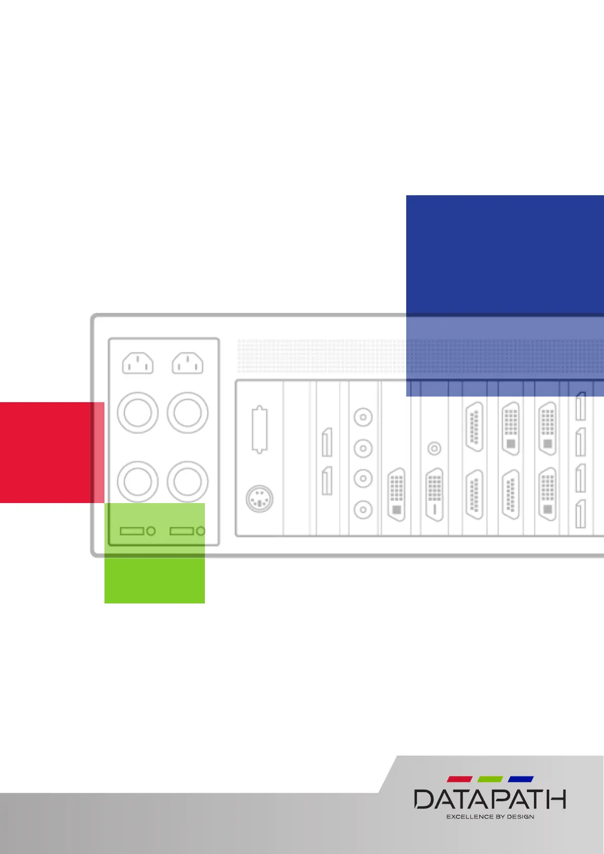
Produktspecifikationer

Varumärke: Datapath
Kategori: Kontroller
Modell: VSN972

Behöver du hjälp?

Om du behöver hjälp med Datapath VSN972 ställ en fråga nedan och andra användare kommer att svara dig


Kontroller Datapath Manualer

Kontroller Manualer

Nyaste Kontroller Manualer