Drayton Twinzone PBTE66 Bruksanvisning
Drayton ej kategoriserat Twinzone PBTE66
Läs gratis den bruksanvisning för Drayton Twinzone PBTE66 (2 sidor) i kategorin ej kategoriserat. Guiden har ansetts hjälpsam av 15 personer och har ett genomsnittsbetyg på 4.8 stjärnor baserat på 4 recensioner. Har du en fråga om Drayton Twinzone PBTE66 eller vill du ställa frågor till andra användare av produkten? Ställ en fråga
Sida 1/2
ZONE
VALVE PACK
WITH
LWC 1
WIRING
CENTRE
CONTENTS
Programmer
Zone V
alve Heating
Zone Valve
Hot Water
Room
Thermostat
Cylinder
Thermostat
LWC 1 Wiring
Centre
Heating Control Pack
with
Switchmaster, Lifestyle or Tempus Programmer
INSTALLATION
AND
WIRING GUIDE
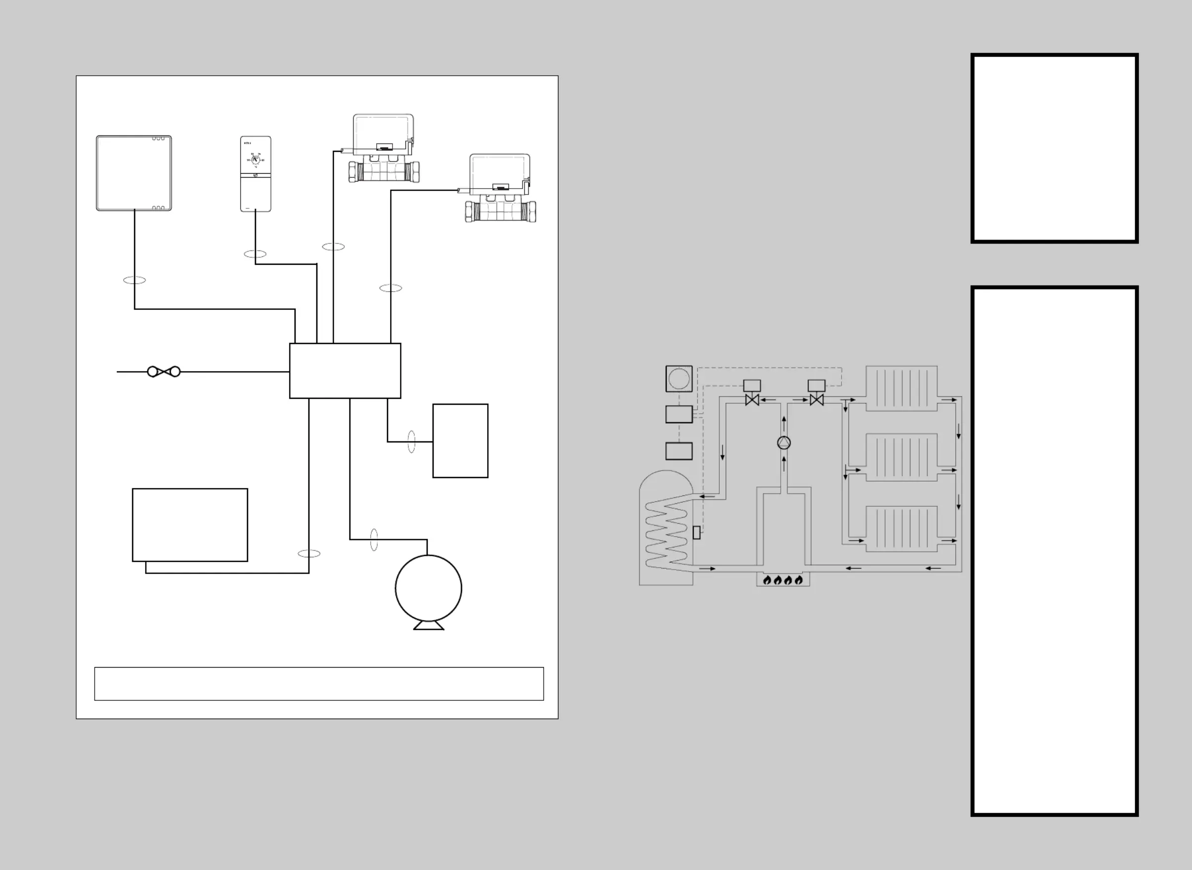
FIRST FIX DIAGRAM
LWC 1 WIRING
CENTRE
PROGRAMMER
BOILER
PUMP
ROOM STAT
HTS 3
CYLINDER
STAT
3 CORE
+ EARTH
2 CORE
2 CORE
+ EARTH
2 CORE
+ EARTH
MAINS 230V. AV
FUSED 3A
NOTE:1.The 2-port Zone Valves are supplied with 30" of cable
DHW
VALVE
090-667 Iss C
28mm
5 CORE
+ EARTH
22mm
4 CORE
+ EARTH
28mm
5 CORE
+ EARTH
22mm
4 CORE
+ EARTH
4 CORE
SM 400LP 112
SM 600LP 241
SM 805LP 522Tempus 6
SM 905LP 722Tempus 7
Lifestyle
Wiring Centre
Programmer
Cylinder
Thermostat
Boiler
Hot Water ValveHeating Valve
Pump
Room
Thermostat
B A
B A
HTG
VALVE
Invensys Controls Europe
Customer Service Tel: 0845 130 5522
Technical Helpline Tel: 0845 130 7722
Email: [email protected]
Website: www.draytoncontrols.co.uk
Produktspecifikationer
| Varumärke: | Drayton |
| Kategori: | ej kategoriserat |
| Modell: | Twinzone PBTE66 |
Behöver du hjälp?
Om du behöver hjälp med Drayton Twinzone PBTE66 ställ en fråga nedan och andra användare kommer att svara dig
ej kategoriserat Drayton Manualer

21 September 2025
5 Augusti 2025
4 Augusti 2025
ej kategoriserat Manualer
Nyaste ej kategoriserat Manualer
3 April 2026
3 April 2026
3 April 2026
3 April 2026
3 April 2026
3 April 2026
3 April 2026
3 April 2026
3 April 2026