Flir M332 Bruksanvisning
Flir
övervakningskamera
M332
Läs nedan 📖 manual på svenska för Flir M332 (110 sidor) i kategorin övervakningskamera. Denna guide var användbar för 17 personer och betygsatt med 3.5 stjärnor i genomsnitt av 9 användare
Sida 1/110

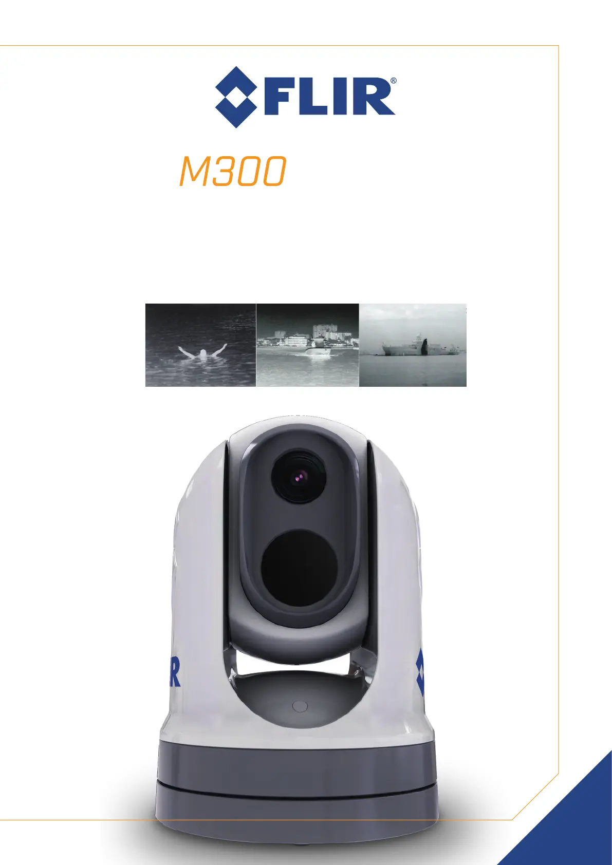
INSTALLATION & OPERATION
INSTRUCTIONS
SERIES
© 2019 FLIR Systems, Inc.
English (en-US) | Date: 10-2019 | Document number: 71004-2


T rademarkandpatentsnotice
Raymarine,T acktick,ClearPulse,T ruzoom,SeaT alk,SeaT alk hs,SeaT alkng,andMicronet,are
registeredorclaimedtrademarksofRaymarineBelgium.
FLIR,LightHouse,DownVision,SideVision,RealVision,HyperVision,Dragony,Element,
Quantum,Axiom,Instalert,InfraredEverywhere,TheWorld’sSixthSenseandClearCruiseare
registeredorclaimedtrademarksofFLIRSystems,Inc.
Allothertrademarks,tradenames,orcompanynamesreferencedhereinareusedforidentication
onlyandarethepropertyoftheirrespectiveowners.
Thisproductisprotectedbypatents,designpatents,patentspending,ordesignpatentspending.
Patentsnotice
ThisproductiscoveredbyoneormoreofUSPatentNos:7470904;7034301;6812465;7470902;
6929410andotherpatentspending,ordesignpatentspending.
FairUseStatement
Y oumayprintnomorethanthreecopiesofthismanualforyourownuse.Y oumaynotmakeany
furthercopiesordistributeorusethemanualinanyotherwayincludingwithoutlimitationexploiting
themanualcommerciallyorgivingorsellingcopiestothirdparties.
Exportcontrol
M300SeriesthermalcamerasarecontrolledbyUSexportlaws.
Therearespecialversionsofthesystemthatareapprovedforinternationaldistributionandtravel.
PleasecontactFLIRcustomersupportifyouhaveanyquestions.
ContactdetailscanbefoundontheFLIRwebsite,www.ir.com.
ExportAdministrationRegulations(EAR)
ThisdocumentiscontrolledtoFLIRTechnologyLevel1.Theinformationcontainedinthisdocument
pertainstoadualuseproductcontrolledforexportbytheExportAdministrationRegulations(EAR).
FLIRtradesecretscontainedhereinaresubjecttodisclosurerestrictionsasamatteroflaw.Diversion
contrarytoUSlawisprohibited.USDepartmentofCommerceauthorizationisnotrequiredpriorto
exportortransfertoforeignpersonsorpartiesunlessotherwiseprohibited.
Softwareupdates
Important:ChecktheFLIRwebsiteforthelatestsoftwarereleasesforyourproduct.
www.ir.com/marine/support
Producthandbooks
ThelatestversionsofallEnglishandtranslatedhandbooksareavailabletodownloadinPDF
formatfromwww.ir.com/marine/support.
Pleasecheckthewebsitetoensureyouhavethelatesthandbooks.
Copyright©2019FLIRSystems,Inc.Allrightsreserved.
English(en-US)
Documentnumber:71004-2
AB;18839;2019-10-28T11:10:07


Mountingthecamerawiththeoptionalmountingriser.................................................34
3.6JCU-2Mounting...................................................................................................37
Locationrequirements.......................................................................................................37
Removingthekeypadmat...............................................................................................38
Flushmountingthekeypad..............................................................................................38
Surfacemountingthekeypad..........................................................................................40
Fittingthekeypadmat.....................................................................................................41
Chapter4Connections.......................................................................................43
4.1Generalcablingguidance...................................................................................44
Cabletypesandlength....................................................................................................44
Cablerouting.....................................................................................................................44
Strainrelief........................................................................................................................44
Circuitisolation..................................................................................................................44
Cableshielding..................................................................................................................45
HD-SDIcableconnection.................................................................................................45
4.2Connectionsoverview..........................................................................................45
Connectingcables.............................................................................................................46
Orientationofright-angledconnectors............................................................................47
4.3Videoconnections...............................................................................................47
Videoandnetworkcables...............................................................................................49
4.4NMEA0183connection......................................................................................49
4.5T ypicalsystems....................................................................................................51
4.6Networkconnections...........................................................................................51
Non-RayNetsystems.........................................................................................................52
RayNetsystemswithRaymarineLightHouse3multifunctiondisplays(MFDs)...........56
4.7Powerconnection................................................................................................59
Powerdistribution..............................................................................................................60
In-linefuseandthermalbreakerratings.........................................................................63
Grounding—Dedicateddrainwire.................................................................................63
Chapter5Cameracontroloptionsandstatusicons...................................65
5.1Cameracontroloptions.......................................................................................66
5.2Cameraimage.....................................................................................................66
ThermalCamera................................................................................................................66
Camerastatusicons.........................................................................................................67
Imageadjustments............................................................................................................71
5.3Cameracontrol....................................................................................................73
Pan,tiltandzoom............................................................................................................73
Homeposition...................................................................................................................73
Surveillancemode.............................................................................................................74
Chapter6Webinterfaceoperation..................................................................75
6

6.1Webbrowseruserinterfaceoverview...............................................................76
6.2Settingupanetworkconnectiontothecamera..............................................76
6.3LoggingintotheWebbrowseruserinterface................................................77
Firsttimelogin..................................................................................................................78
6.4Videofeed...........................................................................................................78
6.5Camerasettingsmenus......................................................................................79
6.6Systemsettings...................................................................................................79
6.7T roubleshoot.........................................................................................................80
SettingastaticIPaddress..............................................................................................80
Chapter7JCU-2operation................................................................................81
7.1MainMenu...........................................................................................................82
7.2JCU–2controlsoverview....................................................................................82
ConguringJCU-2user-programmablebuttons(UPBs).................................................84
Chapter8MFDoperation...................................................................................87
8.1Overview...............................................................................................................88
8.2ClearCruisethermalanalytics.............................................................................88
8.3Auto-tracking........................................................................................................89
Chapter9Maintenance.......................................................................................91
9.1Serviceandmaintenance...................................................................................92
9.2Cleaningthecamera...........................................................................................92
Chapter10Systemchecksandtroubleshooting..........................................93
10.1Thermalcameratroubleshooting......................................................................94
10.2FLIRMaritimeproductsupportandservicing................................................95
Chapter11Technicalspecication...................................................................97
11.1M300Seriescameras.......................................................................................98
T echnicalspecication......................................................................................................98
Videospecication............................................................................................................98
11.2JCU-2.................................................................................................................99
T echnicalspecication......................................................................................................99
Chapter12Sparesandaccessories..............................................................101
12.1M300Seriescamerasparesandaccessories.............................................102
12.2FLIRnetworkingaccessories..........................................................................103
12.3RayNettoRJ45adaptercables....................................................................104
12.4RayNettoRayNetcablesandconnectors...................................................105
7

Chapter1:Importantinformation
Warning:Productinstallationandoperation
•Thisproductmustbeinstalledandoperatedinaccordancewiththe
instructionsprovided.Failuretodosocouldresultinpersonalinjury,
damagetoyourvesseland/orpoorproductperformance.
•Certiedinstallationbyanapprovedinstallerisrecommended.Acertied
installationqualiesforenhancedproductwarrantybenets.Contactyour
dealerforfurtherdetails,andrefertotheseparatewarrantydocument
packedwithyourproduct.
Warning:Corrosion
Toavoidacceleratedgalvaniccorrosionoftheproduct,ensurethata
non-metallicisolationmountisusedwhenttingtheproductdirectlytolarge
stainlesssteelplatforms/mounts,ordirectlytosteelconstructionvessels.
Warning:Potentialignitionsource
ThisproductisNOTapprovedforuseinhazardous/ammableatmospheres.
DoNOTinstallinahazardous/ammableatmosphere(suchasinanengine
roomornearfueltanks).
Warning:Productgrounding
Beforeapplyingpowertothisproduct,ensureithasbeencorrectly
grounded,inaccordancewiththeinstructionsprovided.
Warning:Positivegroundsystems
Donotconnectthisunittoasystemwhichhaspositivegrounding.
Warning:Powersupplyvoltage
Connectingthisproducttoavoltagesupplygreaterthanthespecied
maximumratingmaycausepermanentdamagetotheunit.Refertothe
Technicalspecicationsectionforvoltagerating.
Warning:Switchoffpowersupply
Ensurethevessel’spowersupplyisswitchedOFFbeforestartingtoinstall
thisproduct.DoNOTconnectordisconnectequipmentwiththepower
switchedon,unlessinstructedinthisdocument.
Warning:Entrapmenthazard
Thisproductfeaturesmovingpartsthatprovideapotentialentrapment
hazard.Keepclearofmovingpartsatalltimes.
Warning:Ensuresafenavigation
Thisproductisintendedonlyasanaidtonavigationandmustneverbe
usedinpreferencetosoundnavigationaljudgment.Onlyofcialgovernment
chartsandnoticestomarinerscontainallthecurrentinformationneeded
forsafenavigation,andthecaptainisresponsiblefortheirprudentuse.
Itistheuser’sresponsibilitytouseofcialgovernmentcharts,noticesto
mariners,cautionandpropernavigationalskillwhenoperatingthisorany
otherFLIRproduct.
Importantinformation 9

Warning:Maintainapermanentwatch
Alwaysmaintainapermanentwatch,thiswillallowyoutorespondto
situationsastheydevelop.Failuretomaintainapermanentwatchputs
yourself,yourvesselandothersatseriousriskofharm.
Caution:Donotopentheunit
Theunitisfactorysealedtoprotectagainstatmospherichumidity,suspended
particulatesandothercontaminates.Itisimportantthatyoudonotopen
theunitorremovethecasingforanyreason.Openingtheunitwill:
•compromisethesealwithpossibledamagetotheunit,and
•voidthemanufacturer’swarranty .
Caution:Powersupplyprotection
Wheninstallingthisproductensurethepowersourceisadequatelyprotected
bymeansofasuitably-ratedfuseorautomaticcircuitbreaker.
Caution:Serviceandmaintenance
Thisproductcontainsnouserserviceablecomponents.Pleasereferall
maintenanceandrepairtoauthorizedFLIRdealers.Unauthorizedrepair
mayaffectyourwarranty.
Caution:Suncovers
•Ifyourproductissuppliedwithasuncover,toprotectagainstthe
damagingeffectsofultraviolet(UV)light,alwaystthesuncoverwhen
theproductisnotinuse.
•Toavoidpotentialloss,suncoversmustberemovedwhentravellingat
highspeed,whetherinwaterorwhenthevesselisbeingtowed.
Cleaningthecamera
Thecamerahousingandlenswillrequireoccasionalcleaning.Y oushouldcleanthelenswhen
imagequalitydegradationisnoticedorexcessivecontaminantbuildupisseen.Cleanthe
interfacebetweentheyokeandbaseoftentopreventaccumulationofdebrisorsaltdeposits.
Whencleaningthisproduct:
•DoNOTwipethelenswindowwithadrycloth,orwithabrasivematerialssuchaspaper
orscrubbrushes,asthiscouldscratchthecoating.
•DoNOTuseacidorammoniabasedproducts.
•DoNOTpressurewash.
Particularcareshouldbetakenwhencleaningthelenswindow,thishasaprotective
anti-reectivecoatingwhichmaybedamagedbyimpropercleaning.
1.Switchoffthepowertotheunit.
2.Cleanthecamerabodywithaclean,softcottoncloth.Y oucanmoistentheclothand
useamilddetergentifrequired.
3.Cleanthecameralens.
•Rinsethelenswithfreshwatertoremovealldirtparticlesandsaltdeposits,and
allowtodrynaturally.
•Ifanyspotsorsmearsremain,verygentlywipethelenswindowwithacleanmicrobre
clothorsoftcottoncloth.
•Ifnecessary,useisopropylalcohol(IPA)oramilddetergenttoremoveanyremaining
spotsormarks.
10

Suppressionferrites
•Cablesmaybepre-ttedorsuppliedwithsuppressionferrites.Theseareimportantfor
correctEMCperformance.Ifferritesaresuppliedseparatelytothecables(i.e.not
pre-tted),youmusttthesuppliedferrites,usingthesuppliedinstructions.
•Ifaferritehastoberemovedforanypurpose(e.g.installationormaintenance),itmustbe
replacedintheoriginalpositionbeforetheproductisused.
•Useonlyferritesofthecorrecttype,suppliedbythemanufactureroritsauthorizeddealers.
•Whereaninstallationrequiresmultipleferritestobeaddedtoacable,additionalcableclips
shouldbeusedtopreventstressontheconnectorsduetotheextraweightofthecable.
•Ifyourcamerainstallationrequireslongcableruns,youmayneedtotadditionalferrites
tomaintainacceptableEMCperformance.
Connectionstootherequipment
Requirementforferritesonnon-FLIRcables
IfyourFLIRequipmentistobeconnectedtootherequipmentusingacablenotsuppliedby
FLIR,asuppressionferriteMUSTalwaysbeattachedtothecableneartheFLIRunit.
DeclarationofConformity
FLIRBelgiumBVBAdeclaresthatthefollowingproductsareincompliancewiththeEMC
Directive2014/30/EU:
•M364C30Hzdualpayloadthermalcamera,partnumberE70518
•M364C9Hzdualpayloadthermalcamera,partnumberE70519
•M364C30Hzdualpayloadthermalcamera,partnumberE70520
•M364C9Hzdualpayloadthermalcamera,partnumberE70521
•M36430Hzsinglepayloadthermalcamera,partnumberE70525
•M3649Hzsinglepayloadthermalcamera,partnumberE70526
•M33230Hzsinglepayloadthermalcamera,partnumberE70527
•M3329Hzsinglepayloadthermalcamera,partnumberE70528
•M300C30Hzsinglepayloadcamera,partnumberE70605
TheoriginalDeclarationofConformitycerticatemaybeviewedontherelevantproduct
pageatwww.ir.com/marine.
Productdisposal
DisposeofthisproductinaccordancewiththeWEEEDirective.
TheWasteElectricalandElectronicEquipment(WEEE)Directiverequirestherecycling
ofwasteelectricalandelectronicequipmentwhichcontainsmaterials,componentsand
substancesthatmaybehazardousandpresentarisktohumanhealthandtheenvironment
whenWEEEisnothandledcorrectly.
Equipmentmarkedwiththecrossed-outwheeledbinsymbolindicatesthat
theequipmentshouldnotbedisposedofinunsortedhouseholdwaste.
Localauthoritiesinmanyregionshaveestablishedcollectionschemes
underwhichresidentscandisposeofwasteelectricalandelectronic
equipmentatarecyclingcenterorothercollectionpoint.
Formoreinformationaboutsuitablecollectionpointsforwasteelectrical
andelectronicequipmentinyourregion,refertotheRaymarinewebsite:
www.raymarine.eu/recycling.
12

2.1Documentinformation
Thisdocumentcontainsimportantinformationrelatedtotheinstallationandoperationof
yourFLIRproduct.
Thedocumentincludesinformationtohelpyou:
•planyourinstallationandensureyouhaveallthenecessaryequipment;
•installandconnectyourproductaspartofawidersystemofconnectedmarineelectronics;
•useyourproductalongwithanappropriatevideomonitor,joystickcontrolunit(JCU),
webbrowser,ormultifunctiondisplay(MFD).
•troubleshootproblemsandobtaintechnicalsupportifrequired.
ThisandotherFLIRproductdocumentsareavailabletodownloadinPDFformatfrom
www.ir.com/marine/support.
Applicableproducts
Thisdocumentisapplicabletothefollowingproducts:
SinglePayload
Partnumber Name D
E70528 M332(9Hz)
E70527 M332(30Hz)
•24°FieldofView
(FOV)
•320pxthermalsensor
resolution
E70526 M364(9Hz)
E70525 M364(30Hz)
•24°FieldofView
(FOV)
•640pxthermalsensor
resolution
SinglePayload
Partnumber Name D
E70605 M300C(30Hz) DLTVvisiblelightoptical
sensorwith1080p
resolutionand30xzoom
16

DualPayload
Partnumber Name D
E70521 M364CLR(9Hz)
E70520 M364CLR(30Hz)
•18°FieldofView
(FOV)
•640pxthermalsensor
resolution
•DLTVvisiblelight
opticalsensorwith
1080presolutionand
30xzoom
E70519 M364C(9Hz)
E70518 M364C(30Hz)
•24°FieldofView
(FOV)
•640pxthermalsensor
resolution
•DLTVvisiblelight
opticalsensorwith
1080presolutionand
30xzoom
Additionalsystemcomponents
M300Seriesthermalcamerascanbeusedinconjunctionwiththefollowingoptionalitems,
availableseparatelyfromFLIR:
•JCU-2joystickcontrolunit:aremotekeypadforFLIRthermalcameras(500–0398–10).The
keypadinteractsdirectlywithsupportedthermalcameras,anddoesnotrequireanyother
products(suchasanMFD)tobepresentonthenetwork.EachJCU-2keypadcanbe
pairedwithmultiplethermalcameras,andeachcameracanbepairedtomultiplekeypads.
•JCU-1andJCU-3:Formoreinformationontheseremotekeypads,referto:2.5
Compatiblejoystickcontrollers(JCU)
Productdocumentation
Thefollowingdocumentationisapplicabletoyourproduct:
Description
M300ThermalCameraInstallationandOperationInstructions
InstallationandoperationofanM300Seriesthermalcameraand
connectiontoawidersystemofmarineelectronics.
71004
M300Seriessurfacemountingtemplate
CutouttemplateformountinganM300Seriesthermalcamera.
77005
M300Seriesrisermountingtemplate
Drilltemplateformountingthecamerariser.
77006
LightHouse™3MFDAdvancedOperationInstructions
DetailstheoperationoftheVideoapplicationfor(Raymarine®)
LightHouse™3-compatiblemultifunctiondisplays.
81370
2.2Systemoverview
Thecamerahasaexiblearrayofconnectionoptionstoenableyoutointegrateitwithyour
electronicssystem.
Withtherightcombinationofdevicesandconnections,youcanviewandcontrolthecamera’s
imagefromthemostconvenientlocationsonyourvessel.
Thefollowingillustrationshowsaverytypicalinstallationscenario.Formoresystem
congurationexamples,rangingfromsmalltolargesystems,referto:4.6Network
connections
Documentandproductinformation 17

Foranoverviewofthecamera’svideoconnectionoptions,referto:4.3Videoconnections
Note:Powerconnectionsarenotshowninthisillustration.Thecameraandtheother
devicesshownrequiretheirowndedicatedpowerconnection.
1M300Seriescamera
2Joystickcontrolunit(e.g.JCU-2),availableseparately
3HD-SDIdisplay,availableseparatelyfromthird-partyretailers
4EthernetnetworkswitchwithPoE,availableseparatelyas4141042
5RayNet-to-RJ45adaptercable(120mm/4.7in.)(suppliedwithcamera)
6Right-angledRayNet-to-RayNetcable(3m/9.8ft)(suppliedwithcamera)
7RJ45-to-RJ45networkcable,availableseparatelyinvariouslengths—
refertop.103—FLIRnetworkingaccessories
8 Right-angledHD-SDIcable(withBNCconnectors)(3m/9.8ft)(supplied
withcamera)
2.3Productoverview
M300(singlepayload)
TheM300Seriessinglepayloadvariantisamaritimecameraequippedwitheitheravisibleor
thermalimagingsystem(dependingonchosenmodel),foruseonnearlyanykindofvessel.
Thecamerawillhaveoneofthefollowingtypesofimagingcore,dependingonthechosen
model:
•Visible—providesaclearcolorimageindaylightconditions.Forexample,avisible
cameracanhelpyoumaintainawatchofyoursurroundings,orzoominondistantobjects.
•Thermal—providesaclearimageinlow-lightandno-lightconditions.Forexample,a
thermalcameracanhelpyounavigateatnightoridentifyobstaclesinareasoflow
visibilityoreventotaldarkness.
18

1.Tiltassembly.
2.Cameralenswindow.
3.Panassembly.
TheM300Seriessystemhasthefollowingkeyfunctionsandfeatures:
•IPconnectivitytosimplifyinstallationandsystemintegration.
•4simultaneousvideooutputs,includinganH264-encodedIPvideostream—formore
information,referto:p.47—Videoconnections
•Panandtiltoperationswithdedicatedjoystickcontrolunit,multifunctiondisplay(MFD),
orwebbrowser.
•2axismechanicalcamerastabilizationtosuitchangingconditions.
•Presetmodes(Scenes)optimizedforprevailingconditions.
•ColorThermalVision(CTV)blendingmode—blendsthermalandvisiblelightcolorvideo
feedsforenhancedidenticationofbuoys,vesselsandothertargetsatnight.
•MultiSpectralDynamicImaging(MSX)blendingmode—addsspecicdetailsfromthe
visiblelightvideofeedinrealtimetothethermalvideofeed,fordetectingandsharpening
theedgesofobjectsinthethermalvideofeed.
•ClearCruise™ObjectDetection—intelligentthermalanalyticstechnology;providesaudible
andvisualalertswhen“non-water”objectsareidentiedinthescene.(Requiresa
Raymarine®MFDrunningLightHouse™3.10softwareorlater.)
•ClearCruise™AugmentedReality—featureplaceslayersofdigitalinformationdirectlyover
thetopofthevideofeed.Vesseldataisusedtogenerateinformativetextandimages
(ags)thatoverlapreal-lifeobjects.(RequiresaRaymarine®MFDrunningLightHouse™
3.10softwareorlater.)
•Automaticwindowheaterstode-icethelenswindowincoldweather.
•12Vor24Vdcpower.
Documentandproductinformation 19

•MultiSpectralDynamicImaging(MSX)blendingmode—addsspecicdetailsfromthe
visiblelightvideofeedinrealtimetothethermalvideofeed,fordetectingandsharpening
theedgesofobjectsinthethermalvideofeed.
•ClearCruise™ObjectDetection—intelligentthermalanalyticstechnology;providesaudible
andvisualalertswhen“non-water”objectsareidentiedinthescene.(Requiresa
Raymarine®MFDrunningLightHouse™3.10softwareorlater.)
•ClearCruise™AugmentedReality—placeslayersofvesseldatadirectlyoverthevideo
feed,intheformoftextandimages(ags)thatoverlapreal-lifeobjects.(Requiresa
Raymarine®MFDrunningLightHouse™3.10softwareorlater.)
•Automaticwindowheaterstode-icethelenswindowincoldweather.
•12Vor24Vdcpower.
2.4Partssupplied
M300-Seriescamera
Documentandproductinformation 21

1.M300Camera
2.Camerabase-seal
3.Cameragasket
4.RayNet-to-RJ45adaptorcable120mm(4.72in.)
5.Right-angledRayNet-to-RayNetcable3m(9.8ft.)
6.Right-angledHD-SDIvideocable(withBNCconnectors)3m(9.8ft.)
7.Right-angledpower/NMEA0183/videocable3m(9.8ft.)
8.Mountingriser
9.3xcameraxings:nuts,domenuts,springandatwashers,threadedstuds
10.2xself-adhesivedecals(forball-downmountingonly)
11.Documentationpack
Partssupplied—JCU-2(availableseparately)
Thepartssuppliedwiththeoptionalkeypadareshownbelow.
1.JCU-2keypad
2.Keypadmat
3.Mountinggasket
4.4xmountingscrews,rubberwashers,mountingclamps
5.Cableglandnut
6.RJ45-to-RJ45Ethernetcable,7.6m(25ft)
7.Documentationpack
22

2.5Compatiblejoystickcontrollers(JCU)
Ajoystickcontrolunit(JCU)isavailabletopurchaseasanoptionalaccessory.Thisenables
youtocontrolthecameraremotely.
JCUvariant Partnumber Moreinformation&manuals
JCU-1 500-0385-00 www.raymarine.com/view/index.cfm?id=17603
JCU-2 500-0398-10 www.ir.com/products/jcu2/
JCU-3 A80510 www.ir.com/products/jcu3/
2.6Compatiblemultifunctiondisplays
ThecameraimagecanbeviewedandcontrolleddirectlyfromaRaymarinemultifunction
display(MFD).
Note:ARaymarine®LightHouseMFDisnotrequiredtouseanM300Seriescamera.
Howevercertaincamerafeaturesmaynotbeaccessiblewithoutone.
ThisproductiscompatiblewiththefollowingRaymarine®LightHouse3multifunctiondisplays:
•eSSeries(upgradedfromLightHouse2toLightHouse3).
•gSSeries(upgradedfromLightHouse2toLightHouse3).
•Axiom
•AxiomPro
•AxiomXL
Multifunctiondisplaysoftwarerequirements
TousethisproductwithaRaymarine®multifunctiondisplay(MFD),ensurethatyourMFDis
runningVersion3.10orlateroftheLightHouse™3software.
Note:
•ThelatestLightHouse™MFDsoftwarecanbeobtainedbyvisiting
www.raymarine.com/software.
Documentandproductinformation 23

24

Chapter3:Installation
Chaptercontents
•3.1Generallocationrequirementsonpage26
•3.2Toolsrequiredonpage27
•3.3Productdimensionsonpage28
•3.4Cameraorientationonpage31
•3.5Cameramountingonpage31
•3.6JCU-2Mountingonpage37
Installation 25

•Power—tokeepcablerunstoaminimum,theproductmustbelocatedascloseas
possibletothevessel’sdcpowersupply.
•Mountingsurface—ensuretheproductisadequatelysupportedonasecuresurface.
RefertotheweightinformationprovidedintheT echnicalspecicationforthisproductand
ensurethattheintendedmountingsurfaceissuitableforbearingtheproductweight.Do
NOTmountunitsorcutholesinplaceswhichmaydamagethestructureofthevessel.
Compasssafedistance
Topreventpotentialinterferencewiththevessel'smagneticcompasses,ensureanadequate
distanceismaintainedfromtheproduct.
Whenchoosingasuitablelocationfortheproductyoushouldaimtomaintainthemaximum
possibledistancefromanycompasses.Typicallythisdistanceshouldbeatleast1m(3.3ft)
inalldirections.Howeverforsomesmallervesselsitmaynotbepossibletolocatethe
productthisfarawayfromacompass.Inthissituation,whenchoosingtheinstallation
locationforyourproduct,ensurethatthecompassisnotaffectedbytheproductwhen
itisinapoweredstate.
3.2T oolsrequired
Thefollowingtoolsarerequiredforinstallation.
1 Drill
2 10mm(0.39in.)spanner
Installation 27

3Drillbit(appropriatesizedependentonthicknessandmaterialofmounting
surface)
4 Jigsaw
5Pozi-drivescrewdriver
6 Thread-lock
7 50mm(2in.)Holesaw
3.3Productdimensions
M300Series
28

JCU-2(availableseparately)
Productdimensions
Dimensionent
A90.8mm(3.57in.)
B142.8mm(5.62in.)
C48.9mm(1.93in.)
D75.8mm(2.98in.)
E88.7mm(3.49in.)
F 37.9mm(1.49in.)
G77.5mm(3.05in.)
H7.6m(25ft.)
I 128.5mm(5.06in.)
J 77.0mm(3.03in.)
30

3.4Cameraorientation
Thecameracanbemountedin2orientationsinformallyknownas“Ballup”and“Balldown”.
Ball-up:Thecameraismountedontopof
themountingsurface.
Ball-down:Thecameraissuspendedupside
down,belowthemountingsurface.
Thedefaultvideoimageorientationisfortheball-upconguration;ifthecameraistobe
mountedintheball-downcongurationthenthevideoimagemustberotated.T orotate
thevideoimage,youmusteither:
•usethecamera’swebbrowseruserinterfacetosettheappropriateoption(see
p.75—Webinterfaceoperation
),or
•ifyoursystemincludesaRaymarinemultifunctiondisplay(MFD),usetheMFD’sCamera
apptosettheappropriateoption(refertoyourMFDOperationInstructions).
3.5Cameramounting
Locationrequirements
Whenplanningtheinstallationlocation,considerthefollowingpoints:
•Thecameraiswaterproof,andappropriateforabovedecksmounting.
•Whenmountingthecamerainaball-downposition,ensurethatthecameraisinstalled
withadequatedrainagesothatstandingwaterdoesnotcollectinthebase.
•Ensurethecameraisinstalledinalocationthatwillallowittobeaccessedforregular
periodiccleaning(fresh-waterrinse),inspectionofmountingpointintegrityandmechanical
soundness,andpreventativemaintenance.
•Theunderside(inside)ofthecompartmentordeckontowhichthecameraismountedmust
beweather-tight.Y oumustensureprotectionfromwateringresstocablesandconnections.
•Themountingsurfacemustbehorizontal.
•Ifyoucannotaccessbothsidesofthemountingsurface,thenyouwillneedtomountthe
camera“topdown”usingthemountingrisersuppliedwiththecamera.
•Thecamerashouldbemountedashighaspractical,butwithoutinterferingwithanyradar,
navigationalorcommunicationselectronics.
•Choosealocationthatwillprovidethemostunobstructedviewinalldirections.
Installation 31

•Choosealocationasclosetothevessel’scenterlineaspossible.Thisprovidesa
symmetricalviewwhenlookingforwardoraft.
•Selectalocationforthecamerathatisatleast1m(39.4in.)fromanymagneticcompass.
•Selectalocationthatisatleast1m(3ft)fromdevicesthatmaycauseinterference,such
asmotors,generatorsandradiotransmitters/receivers.
•IfinstallinganoptionalJCU,selectalocationfortheJCUthatisatleast1m(39.4
in.)fromanymagneticcompass.
Note:Ifyouwanttomakecableconnectionstothecamerabeforemountingittoyour
vessel(forexample,totestthecamera),rstattachthethreethreadedstudstothebase
(seep.32—Mountingthecamera).Thiswillhelptoprotectthecableconnectorson
thebaseofthecamera,andalsoprovidesastableplatform,helpingtopreventdamage
causedbytheunitrollingofftheedgeoftheworksurface.
Mountingthecamera
Usetheseinstructionstomountthecameraunitinposition.
32

2.Installthe3xthreadedstudsintothebaseofthecamerawiththread-lockingcompound.
Ifrequired,youcanusestudsofadifferentlengthtosuityourinstallation.
3.Slidethefoamgasketoverthethreadedstuds,andstickitrmlyintoplaceonthe
camera’sbase.
4.Connectthepowersupplycable,BNCvideocableandnetworkcablestothecamera,
andthreadthecablesthroughthecentralhole.
5.Placethecameraonthemountingsurfacesothethreadedstudsextendthroughthe
drilledholes.
6.Maketherequiredconnectionswiththefreeendsofthecables.
7.Slideaatwasher,andthenaspringwasher,ontoeachstud.
8.Securethecamerabodytothemountingsurfacewiththesuppliednuts,ensuringthatthe
sealremainscorrectlypositionedonthecamera’sbase.
Tightenthenutstoatorqueof5.0N·m(3.7lbf·ft).
Domecappednutsareprovidedforaneatersolutionwherethemountingisexposedto
view.
Mountingthecamerawiththeoptionalmountingriser
Theoptionalmountingriserisusedwhenaccesstotheundersideofthemountingsurfaceis
restricted.Usetheinstructionsbelowtomountthecameraunitusingthemountingriser.
34

1.Usingthetemplateprovided,markanddrilltheholesformountingtheriser.
•Notethecameraforwardmarkingonthetopsurfaceoftheriser.Y oumustensure
thattheriserismountedsothatthecameraisorientedproperlyrelativetothebow
ofthevessel.
•Onlydrilltheoptionalcableroutingholeinthemountingsurfaceifyouintendtoroute
thecablesthroughthebaseoftheriser,ratherthanthroughthesideoftheriser.
2.Installthe3xthreadedstudsintothebaseofthecamera.Donotusethreadlocking
compound,asthismaydamagetheplasticriser.
3.Slidethefoamgasketoverthethreadedstuds,andpushitrmlyintoplaceonthe
camera’sbase.
4.Placethecameraontopoftheriser,sothethreadedstudsextendthroughthethree
holesintheriser’stopsurface.Checkthatthefoamgasketremainsrmlyinplace.
•Notethecameraforwardmarkingonthetopsurfaceoftheriser.Y oumustensure
thattheriserismountedsothatthecameraisorientedproperlyrelativetothebow
ofthevessel.
Installation 35

Note:Thesuppliedgasketprovidesasealbetweentheunitandasuitablyatandstiff
mountingsurfaceorbinnacle.Thegasketshouldbeusedinallinstallations.Itmayalso
benecessarytouseamarine-gradesealantifthemountingsurfaceorbinnacleisnot
entirelyatandstifforhasaroughsurfacenish.
Surfacemountingthekeypad
Surfacemountingprovidesauniforminstallationwheretheproductsprotrude,usuallybythe
thicknessofthebezel,fromthemountingsurface.
1.Checktheselectedlocationfortheunit.Aclear,atareawithsuitableclearancebehind
thepanelisrequired.
2.Beforemodifyingthemountingsurface,refertothedimensionssuppliedinthisdocument
toensurethereisenoughspacefortheunitandallcables.
3.Fixthesuppliedmountingtemplatetotheselectedlocation,usingmaskingorself
adhesivetape.
4.Drill4holesasindicatedonthemountingtemplatetoacceptthexings.
5.Usingasuitableholesaw,makeaholeineachcornerofthecut-outarea.
6.Usingasuitablesaw,cutalongtheinsideedgeofthecut-outline.
7.Ensurethattheunittsintotheremovedareaandthenremoveroughedges.
8.Placethesuppliedgasketontotherearofthekeypad,ensuringthemountingholes
arealigned.
40

9.Connecttherelevantcablestotheunit.
Formoreinformationonttingthecablereferto
10.Secureusingthexingsprovided.
Note:
Theappropriatetighteningtorqueanddrillbitsizetousedependsonthethicknessofthe
mountingsurfaceandthetypeofmaterialitismadefrom.
Note:
Thesuppliedgasketprovidesasealbetweentheunitandasuitablyatandstiffmounting
surfaceorbinnacle.Thegasketshouldbeusedinallinstallations.Itmayalsobe
necessarytouseamarine-gradesealantifthemountingsurfaceorbinnacleisnotentirely
atandstifforhasaroughsurfacenish.
Fittingthekeypadmat
Y oushouldtthekeypadmataftertheunithasbeensecuredtothemountingsurface.
1.Ensurethekeypadmatisorientatedcorrectly .
2.Slidethekeypadmatoverthejoystickandclickitintoplace,startingwithoneofthe
longeredges.
3.Closetheoppositeendofthekeypadmatintothekeypad,ensuringthatthetabslides
intothenotchprovided.Pushallofthetabsonthelongersidesintotheirnotches(you
shouldhearaclickaseachtabengages).
Installation 41

42

4.1Generalcablingguidance
Cabletypesandlength
Itisimportanttousecablesoftheappropriatetypeandlength
•Unlessotherwisestateduseonlystandardcablesofthecorrecttype,suppliedbyFLIR.
•Ensurethatanynon-FLIRcablesareofthecorrectqualityandgauge.Forexample,longer
powercablerunsmayrequirelargerwiregaugestominimizevoltagedropalongtherun.
Cablerouting
Cablesmustberoutedcorrectly ,tomaximizeperformanceandprolongcablelife.
•DoNOTbendcablesexcessively .Whereverpossible,ensureaminimumbenddiameter
(Ø)of200mm(7.87in)/minimumbendradius(R)of100mm(3.94in).
•Protectallcablesfromphysicaldamageandexposuretoheat.Usetrunkingorconduit
wherepossible.DoNOTruncablesthroughbilgesordoorways,orclosetomoving
orhotobjects.
•Securecablesinplaceusingcableclipsorcableties.Coilanyexcesscableandtieit
outoftheway .
•Whereacablepassesthroughanexposedbulkheadordeckhead,useasuitable
watertightfeed-through.
•DoNOTruncablesneartoenginesoruorescentlights.
•Alwaysroutedatacablesasfarawayaspossiblefrom:
–otherequipmentandcables,
–highcurrentcarryingACandDCpowerlines,
–antennas.
Strainrelief
Useadequatestrainreliefforcablingtoensurethatconnectorsareprotectedfromstrainand
willnotpulloutunderextremeseaconditions.
Circuitisolation
AppropriatecircuitisolationisrequiredforinstallationsusingbothACandDCcurrent:
•Alwaysuseisolatingtransformersoraseparatepower-invertertorunPC’s,processors,
displaysandothersensitiveelectronicinstrumentsordevices.
•AlwaysuseanisolatingtransformerwithWeatherFAXaudiocables.
•Alwaysuseanisolatedpowersupplywhenusinga3rdpartyaudioamplier.
44

•1xdigitalvideofeed,outputviatheHD-SDIconnector.
•1xanalogvideofeed,outputviathecompositevideoBNCconnectoronthecamera’s
powercable.
Connector Videoformat
1CompositevideoBNCconnectoron
camera’spowercable
Analogvideo.
2 RayNet(Ethernet) •H264-encodedIPdigitalvideo(ONVIF
ProleS).
•MPEG-encodedIPdigitalvideo(via
webbrowseronly).
3HD-SDIdeo,HD-SDIformat
(SMPTE-292M).
Note:ItisalsopossibletoconnecttoanHDMI-capabledisplayorothervideodevice,
viaasuitablethird-partyHD-SDItoHDMIconverter.Contactyourdealerorretailerfor
suitabledevicesandcables.
Note:ONVIFproleshelpyoutodeterminewhichIPdigitalvideodevicesarecompatible
withoneanother.FormoreinformationonONVIFproles,referto:www.onvif.org/proles/
Switchingbetweenthermalandvisiblelight(daylight)camerafeeds(dualpayload
cameravariantsonly)
Thedualpayloadcameravariantshaveseparatethermalandvisiblelight(daylight)video
feeds,andyoucanswitchbetweenthese2differentvideofeedsatanytimeusingaJCU,a
webbrowser,oraRaymarineLightHouse3MFD.
48

ItemDeviceCablecolorPort
Input/
output
Positive(+)
/negative
(-)
1 White 1 InputPositive
2Green 1InputNegative
3Y ellow 1Output Positive
4 Brown 1 Output Negative
5 Orange/White 2 InputPositive
6
Camera
Orange/Green 2 InputNegative
7 ** Output Positive
8 ** Output Negative
9**InputPositive
10
NMEAdevice
**InputNegative
11 ** Output Positive
12
NMEAdevice
** Output Negative
Note:
*RefertoinstructionsprovidedwithyourNMEA0183deviceforconnectiondetails.
50

4.5T ypicalsystems
Thecameracanbeconnectedtoavarietyofdigitaloranalogvideosystems,andcontrolled
viaaJCU,awebbrowser,aRaymarinemultifunctiondisplay(MFD),oranycombination
ofthese.
Note:
•Forinformationonhowtoconnecttheproduct,refertothep.45—Connectionsoverview
•Forinformationonavailablecablesandaccessories,refertothe
p.101—Sparesandaccessories
•BasicWebbrowsersystem:Y oucanconnectthecameradirectlytoanIP-capabledevice,
suchasalaptoporPC,usingthesuppliedRayNetcableandRayNet-to-RJ45adapter
cable.Y oucancontrolthecamerathroughtheuserinterface,accessibleviaawebbrowser.
•BasicdigitalvideodisplaysystemwithJCU:Y oucanconnectthecameradirectlytoa
primarydigitalvideodisplayviathecamera’sHD-SDIoutputandthesuppliedBNCcable,
orviaHDMIusingasuitablethird-partyvideoconverter(availableseparatelyfroman
electronicsretailoutlet).
•BasicanalogvideodisplaysystemwithJCU:Y oucanconnectthecameradirectlytoa
primaryanalogvideodisplayviathecamera’scompositeanalogvideooutputusingthe
BNCconnectoronthecamera’spowercable.
•BasicWebbrowsersystemwithJCU:Y oucanconnecttheproducttoanIP-capable
device,suchasalaptoporPC,viaanEthernetswitch(usingthesuppliedRayNetcable
andRayNet-to-RJ45adaptercable),andanadditionalEthernetcable.Y oucancontrol
thecamerathroughtheuserinterfaceaccessibleviaawebbrowser,orwithaJCU
unit,alsoconnectedtotheEthernetswitch.
•BasicRaymarineLightHouse3multifunctiondisplay(MFD)system:Y oucanconnect
theproductdirectlytoaRaymarineLightHouse3MFDusingthesuppliedRayNetcable.
Y oucancontrolthecameradirectlyusingtheMFD.Foramoreexiblesystem,youcan
installaRayNetswitchbetweenthecameraandtheMFD,andaddaJCUunit(also
connectedtotheRayNetswitch)toprovideadditionalcameracontrols.
•Complexsystemwithmultiplecameras,MFDs,andJCUs:WithsufcientRayNetor
Ethernetportsavailableoninstalledswitches,andappropriateRayNetandEthernetcables,
youcanconnectmultiplecameras,MFDs,andJCUstogethertoformanintegratedsystem.
Y oucanuseanyJCUorMFDtocontrolandmonitoranycamera.
4.6Networkconnections
Y ourcamerahasasingleRayNetnetworkconnector.Thisconnectsthecameratoyour
vessel’swiderIPnetwork.Thiscouldbeanexistingthird-partyEthernetnetwork,ora
dedicatedRaymarineRayNetnetwork.
Thedetailsofthenetworkconnectionsbetweenthecamera,videodisplay(webbrowser,
videomonitor,orLightHouse3Raymarinemultifunctiondisplay),controlunit(forexample,a
JCU-2controller)andtherestofyourinstallationdependon:
•Howyouwanttocontrolthecamera(forexample,withawebbrowser,aLightHouse3
Raymarinemultifunctiondisplay ,aJCUcontroller,oracombination).
•Howyouwanttoviewthecamera’sIPvideofeed(forexample,viaalaptop/PCorviaa
LightHouse3Raymarinemultifunctiondisplay,oracombination).
•theequipmentalreadyinstalledonyourvessel(forexample,networkswitcheswithfree
ports,orothercameras).
Thefollowingsectionsshowsomepossiblenetworkconnections,startingwithabasicsystem
withasinglecameradirectlyconnectedtowebbrowser,andnishingwithamorecomplex
multi-camera,multi-display,multi-JCUsystem.
Connections

Non-RayNetsystems
Y oucaninstallyourcameraonavesselthatdoesn’thaveaRayNetnetworkorLightHouse
3Raymarinemultifunctiondisplay(MFD)installed.
Thefollowingexamplesshowpossiblenetworkconnectionsfor:
•Asingle-camerasystemwiththecameraconnecteddirectlytoalaptoporotherdevice
runningawebbrowser(forcameracontrol,andviewingthecamera’sIPvideofeed).
•Asingle-camerasystemcomprisingalaptoporotherdevicerunningawebbrowser(for
cameracontrol,andviewingthecamera’sIPvideofeed),anEthernetnetworkswitchwith
PoE,andanoptionalJCU(availableseparately)foradditionalcameracontrol
•Asingle-camerasystemcomprisingadigitalvideomonitorconnectedviathecamera’s
HD-SDIvideofeed,anEthernetnetworkswitchwithPoE,andaJCU(availableseparately)
forcameracontrol.
•Asingle-camerasystemcomprisingadigitalvideomonitorconnectedviathecamera’s
HD-SDIvideofeedandanHDMIconvertertoallowconnectionviaHDMI.AlsoanEthernet
networkswitchwithPoE,andaJCU(availableseparately)forcameracontrol.
•Asingle-camerasystemcomprisingananalogvideomonitorconnectedviathecamera’s
compositevideofeed(connectedviathepowercable),anEthernetnetworkswitchwith
PoE,andaJCU(availableseparately)forcameracontrol.
Single-camerasystemwithdirectconnectiontowebbrowser
Note:Powerconnectionsarenotshowninthisillustration.Thecameraandtheother
devicesshownrequiretheirowndedicatedpowerconnection.
Description
1Laptop(orotherEthernet-connecteddevicerunningawebbrowser),
availableseparatelyfromthird-partyretailers
2M300Seriescamera
3RayNet-to-RJ45adaptercable(120mm/4.7in.)(suppliedwithcamera)
4RightangledRayNet-to-RayNetcable(3m/9.8ft)(suppliedwithcamera)
52

Single-camerasystemwithwebbrowserandanoptionalJCU
Note:Powerconnectionsarenotshowninthisillustration.Thecameraandtheother
devicesshownrequiretheirowndedicatedpowerconnection.
Description
1M300Seriescamera
2 Joystickcontrolunit(JCU-2),availableseparately
3 Laptop(orotherEthernet-connecteddevicerunningawebbrowser)
4 EthernetnetworkswitchwithPoE
5RJ45-to-RJ45Ethernetcable
6RayNet-to-RJ45adaptercable(120mm/4.7in.)(suppliedwithcamera)
7RightangledRayNet-to-RayNetcable(3m/9.8ft)(suppliedwithcamera)
Single-camerasystemwithdigitalvideo(HD-SDI)monitorandJCU
Forthissystem,adevicerunningawebbrowserisnotrequired.Thecamera’svideofeedis
routedthroughthecamera’sHD-SDIvideoconnectiontoadigitalvideomonitor.Camera
controlisprovidedbyaJCU(availableseparately).
Connections

Note:Powerconnectionsarenotshowninthisillustration.Thecameraandtheother
devicesshownrequiretheirowndedicatedpowerconnection.
Description
1 M300Seriescamera
2Joystickcontrolunit(JCU-2),availableseparately
3Digitalvideo(HD-SDI)monitor,availableseparatelyfromthird-partyretailers
4 EthernetnetworkswitchwithPoE,availableseparately
5RayNet-to-RJ45adaptercable(120mm/4.7in.)(suppliedwithcamera)
6 RayNet-to-RayNetcable,availableseparately
7RJ45–to-RJ45cable,availableseparately
8HD-SDIvideocable(BNCconnectors)(3m/9.8ft.)(suppliedwith
camera)
Single-camerasystemwithdigitalvideo(HDMI)monitorandJCU
Forthissystem,adevicerunningawebbrowserisnotrequired.Thecamera’svideo
feedisroutedthroughthecamera’sHD-SDIvideoconnectionviaathird-partyHD-SDIto
HDMIvideoconverter(notsupplied)toadigitalvideomonitor.Cameracontrolisprovided
byaJCU(availableseparately).
54

Note:Powerconnectionsarenotshowninthisillustration.Thecameraandtheother
devicesshownrequiretheirowndedicatedpowerconnection.
Description
1 M300Seriescamera
2Joystickcontrolunit(JCU-2),availableseparately
3 Analogvideomonitor,availableseparatelyfromthird-partyretailers
4 EthernetnetworkswitchwithPoE,availableseparately
5RayNet-to-RJ45adaptercable(120mm/4.7in.)(suppliedwithcamera)
6 RayNet-to-RayNetcable,availableseparately
7RJ45–to-RJ45cable,availableseparately
8Camera’spowercable(3m/9.8ft.)(suppliedwithcamera)
9BNC-to-BNCvideocable.IfyouarenotusingthesuppliedBNC
cable(3m/9.8ft.)fortheHD-SDIconnection,youcanuseitfor
thiscompositeanalogconnection.Otherwise,obtainasuitablecable,
separatelyfromthird-partyretailers.
RayNetsystemswithRaymarineLightHouse3multifunctiondisplays
(MFDs)
M300-SeriescamerasarecompatiblewithRaymarineLightHouse3multifunctiondisplays
(MFDs)andexistingRayNetnetworks.
Thefollowingexamplesshowpossiblenetworkconnectionsfor:
•asingle-camerasystemcomprisingaRaymarineLightHouse3MFD(forcameracontrol,
andviewingthecamera’sIPvideofeed),aRayNetnetworkswitch,aJCU(available
separately)foradditionalcameracontrol,andaPoweroverEthernet(PoE)Injector.
•amulti-camerasystemcomprisinganHD-SDIvideomonitor,2RaymarineMFDs(available
separately),aRayNetnetworkswitch(availableseparately),2JCUs(availableseparately),
56

Multi-camerasystemwithdigitalvideomonitor,2RaymarineMFDs,2JCUs,anda
webbrowser
Note:Powerconnectionsarenotshowninthisillustration.Thecameraandtheother
devicesshownrequiretheirowndedicatedpowerconnection.
Description
1Laptop(orotherEthernet-connecteddevicerunningawebbrowser),
availableseparatelyfromthird-partyretailers
2 Digitalvideomonitor,availableseparatelyfromthird-partyretailers
3 M300Seriescamera
58

Description
4Joystickcontrolunit(JCU-2),availableseparately
5RaymarineMFD,availableseparately
6 RayNetnetworkswitch,availableseparately
7 RayNet-to-RayNetcable,availableseparately
8RightangledRayNet-to-RayNetcable(3m/9.8ft)(suppliedwithcamera)
9 RJ45–to-RJ45cable,availableseparately
10 PoEinjector(providespowertoJCU-2),availableseparately
11 RayNet-to-RJ45adaptercable,(120mm/4.72in.versionsuppliedwith
camera;otherlengthsavailableseparately)
12 HD-SDIvideocable(BNCconnectors)(3m/9.8ft.)(suppliedwith
camera)
4.7Powerconnection
Powermustbesuppliedtothecamerafromanappropriatepowersource.
Powerconnectionrequirements
•12or24Vdcnominalsupplyvoltage
•Isolatedpowersupply
•Connectedviaanappropriately-ratedthermalbreakerorfusedswitch(refertoInlinefuse
andthermalbreakerratings).
Description Connectsto:
1 Powercable.Product’spowerconnector.
2 Drain/ground(thinblackwire) Vessel’sRFground,ornegativebattery
terminal.
Connections

1 Positive(+)bar
2 Negative(-)bar
3 Circuitbreaker
4 Waterprooffuseholdercontainingasuitably-ratedinlinefusemust
betted.Forsuitablefuserating,referto:In-linefuseandthermal
breakerratings.
Important:
Observetherecommendedfuse/breakerratingsprovidedintheproduct’sdocumentation,
howeverbeawarethatthesuitablefuse/breakerratingisdependentonthenumberof
devicesbeingconnected.
Implementation—directconnectiontobattery
•Whereconnectiontoapowerdistributionpanelisnotpossible,thepowercablesupplied
withyourproductmaybeconnecteddirectlytothevessel'sbattery,viaasuitablyrated
fuseorbreaker.
•ThepowercablesuppliedwithyourproductmayNOTincludeaseparatedrainwire.Ifthis
isthecase,onlythepowercable’sredandblackwiresneedtobeconnected.
•IfthepowercableisNOTsuppliedwithattedinlinefuse,youMUSTtasuitablyrated
fuseorbreakerbetweentheredwireandthebattery’spositiveterminal.
•Refertotheinlinefuseratingsprovidedintheproduct’sdocumentation.
•Ifyouneedtoextendthelengthofthepowercablesuppliedwithyourproduct,ensure
youobservethededicatedPowercableextensionsadviceprovidedintheproduct’s
documentation.
Connections

64

Chapter5:Cameracontroloptionsandstatusicons
Chaptercontents
•5.1Cameracontroloptionsonpage66
•5.2Cameraimageonpage66
•5.3Cameracontrolonpage73
Cameracontroloptionsandstatusicons 65

Camerastatusicons
Thecameraimageincludesiconstoshowthecurrentstatusofthecamera.
Note:
Iconsarecoloredredifthe WhiteHotor
forallotherpalettes.
IconName Description
ThermalCameraIndicatestheThermalCamerafeed
isactive.
Visible/DaylightCameraIndicatestheVisible/Daylight
Camerafeedisactive.
Cameracontroloptionsandstatusicons 67

IconName Description
MirroredViewIndicatesthecamerafeedis
reversedagainsttheverticalaxis.
Polarity Indicatesachangeinimagepolarity.
ColorPalette Indicatesachangeinimagecolor
palette.
NMEABWSMessage ReceivingNMEAmessagesusing
BearingandDistancetoWaypoint,
GreatCircle(BWC)sentenceformat
hasbeenenabled;thisisalso
knownasslewtowaypoint.
NMEARSD ReceivingNMEAmessagesusing
theRadarSystemData(RSD)
sentenceformathasbeenenabled;
thisisalsoknownasradarcursor
tracking.
NMEATTMReceivingNMEAmessagesusing
theNMEAT rackedT argetMessage
(TTM)sentenceformathasbeen
enabled;thisisalsoknownas
radartracking.
PowerDownThecameraisshuttingdown.
Cameracontroloptionsandstatusicons 69

IconName Description
Scene:NightOneoffourscenepresents
(automaticgaincontrolsettings)
optimizedforuseontheopen
wateratnight.
Scene:DockingOneoffourscenepresents
(automaticgaincontrolsettings)
optimizedforusewhentheboatis
dockingatnight.
Scene:DayOneoffourscenepresents
(automaticgaincontrolsettings)
optimizedforuseontheopen
waterduringtheday .
Scene:ContrastOneoffourscenepresents
(automaticgaincontrolsettings)
optimizedforprovidingvisibilityto
smallmovingobjects.
VerticalStabilization Indicatesthegyrostabilization
settingisverticleonly(pointmode),
whichimprovescameraimage
stabilitywhilekeepingthecamera
pointinginthesameposition
relativetothevesselasitturns.
70

•Cross—pressinganywhereonthevideostreamwillpan/tiltthecamerasothelocation
pressedbecomethenewcentreofthestream.
6.5Camerasettingsmenus
Y oucanaccessdifferentcamerasettingsmenusontheleftsideofthevideostream.The
settingscontainedinthesemenupagescanbeusedtocongureyourcamera.
•Video—Editgeneralvideosettings.
•Visible—Editthevisiblecamerasettings.
•Thermal—Editthethermalcamerasettings.
•PTZ(PanTiltZoom)—EditthePanTiltandZoomsettingsandcontrolthecamera.
•VideoAnalytics—EditMVA(MarineVideoAnalytics)andobjectdetectionsettings.
•OSD(OnScreenDisplay)—Edittheon-screenstatussymbolsandiconsdisplayed
onthevideofeed.
6.6Systemsettings
Y oucanaccessadvancedcamerasettingsanddiagnosticinformationbyselecting System
Settingsatthebottomofthescreen.
•Network
•Date&Time
•Users
•JCU
•T emperature
•Cyber
•ONVIF
•Firmware&info
Webinterfaceoperation 79

7.1MainMenu
Y oucanaccessandcontrolthecamera’s MainMenuviaaconnectedJCU-2.Themenu
willbeoverlaidonthevideofeed.
•UsetheMenubuttonontheJCU-2toturntheOSD(onscreendisplay)MainMenu
onoroff.
•TheJoystickcanbeusedtonavigatethroughthemenus.
•PresstherightJoystickbuttontoselecteachmenu.
•PresstheleftJoystickbuttontoexitthemenu.
MainMenuItems
•ParkCamera—thecamerawillpanandtilttoitspredenedParkposition.Thepark
positioncanbeeditedfromtheWebinterface,seep.75—Webinterfaceoperation
•MVA—accessMVA(MarineVideoAnalytics)settings.
•Surveillance—thecamerawillentersurveillancemode,itpanscontinuouslyleftandright
untilitistakenoutofsurveillancemodeoruntiltheJCUmovesthecamera.
•NMEA—enableordisabletheprocessingofmessagesusingtheNMEAinterface.
•Image—accessadvancedimagesettings.
•Settings—accessadvancedcamerasettings.
•Help—opensthehelpmenu.
7.2JCU–2controlsoverview
ThecameracanbecontrolledwithaJCU-2.
Note:
•TheJCU-2joystickcontrolunitisavailableseparatelyasanoptionalaccessory.
•FormoreinformationonothercompatibleJCUunitsreferto
p.23—Compatiblejoystickcontrollers(JCU)
82

•Pushrightjoystickbuttontoselectmenu
item.
•Pushleft/righttochangenumericvalue.
•Pushrightjoystickbuttontotoggleswitch.
•Pushleftjoystickbuttontoexitcurrent
menuitem.
T oNavigateJCULCDMenu
•Pushfore/afttoscrollup/down.
•Pushleftjoystickbuttontoselectmenu
item.
7MENU
•Presstoenableon-screenmenu.
•Presstoexitmenu.
8LCDDISPLAY
•DisplaysJCUinformationandpowermenu
options.
•Usejoysticktointeract.
9HOME
•Presstoreturntohomeposition.
•Pressandholduntilhomeiconashes
tostorenewhome.
10 CAMERA
•Presstoselectactivecamera.
ConguringJCU-2user-programmablebuttons(UPBs)
Note:TheJCU-2joystickcontrolunitisavailableseparatelyasanoptionalaccessory.
TheJCU-2keypad’suser-programmablebuttons(UPBs)canbeconguredusingthe
camera’sWebinterface.FormoreinformationonaccessingtheWebinterfacereferto
p.75—Webinterfaceoperation
Y oucanassignadifferentactiontoeachUPB(forexample,“Verticalstabilization”,or
“Surveillancemode”)onaper-camerabasis.
Note:UPBmappingsapplytoindividualcamerasratherthantospecicJCU-2keypads.
Thismeansthat,ifyouareusingasingleJCU-2keypadtocontroltwoM300Series
cameras,UPBnumber1couldbeconguredtoinitiateadifferentactiononeachcamera.
TocongureJCU-2userprogrammablebuttons(UPBs)usingthecamera’sWebinterface:
1.Fromthecamera’sWebinterface,select
TheSettingsmenusaredisplayed.
2.Fromthemenusatthetopselect JCU.
The JCUsettingpageisdisplayed.
84

3.Fromthe UPBButtonlist,selectthebuttonyouwishtocongure.
4.FromtheUPBActionlist,choosethecameraactionyouwishtoassociatewiththat
UPBbutton.
5.Repeatsteps3and4foreachUPByouwishtocongure.
6.Select SavetosavetheUPBConguration.
JCU-2operation 85

Chapter8:MFDoperation
Chaptercontents
•8.1Overviewonpage88
•8.2ClearCruisethermalanalyticsonpage88
•8.3Auto-trackingonpage89
MFDoperation 87

90

Chapter9:Maintenance
Chaptercontents
•9.1Serviceandmaintenanceonpage92
•9.2Cleaningthecameraonpage92
Maintenance
Produktspecifikationer
Varumärke: | Flir |
Kategori: | övervakningskamera |
Modell: | M332 |
Behöver du hjälp?
Om du behöver hjälp med Flir M332 ställ en fråga nedan och andra användare kommer att svara dig
övervakningskamera Flir Manualer

17 Oktober 2024

2 Oktober 2024

28 September 2024

24 September 2024

13 September 2024

9 September 2024

9 September 2024

5 September 2024

4 September 2024

3 September 2024
övervakningskamera Manualer
- övervakningskamera Bea-fon
- övervakningskamera Infortrend
- övervakningskamera Mach Power
- övervakningskamera Elro
- övervakningskamera Xavax
- övervakningskamera Mobi
- övervakningskamera EtiamPro
- övervakningskamera Edimax
- övervakningskamera Tecno
- övervakningskamera Wisenet
- övervakningskamera Engenius
- övervakningskamera Lumens
- övervakningskamera Perel
- övervakningskamera Chuango
- övervakningskamera Hikvision
Nyaste övervakningskamera Manualer

2 Juni 2025

2 Juni 2025

2 Juni 2025

1 Juni 2025

1 Juni 2025

1 Juni 2025

1 Juni 2025

1 Juni 2025

1 Juni 2025

1 Juni 2025