Gira System 106 Bruksanvisning
Gira Intercomsystem System 106
Läs gratis den bruksanvisning för Gira System 106 (2 sidor) i kategorin Intercomsystem. Guiden har ansetts hjälpsam av 34 personer och har ett genomsnittsbetyg på 4.8 stjärnor baserat på 5 recensioner. Har du en fråga om Gira System 106 eller vill du ställa frågor till andra användare av produkten? Ställ en fråga
Sida 1/2
General safety instructions
These instructions are part of the product
and must remain with the end customer.
Necessary accessories
•System 106 call-button module (Item
no. 555 ...).
•Audio control device (Item no. 1287 00).
•System 106 call-button module, 1-gang
to 4-gang (Item no. 5531 9.., 5532 9..,
5533 9.., 5534 9..).
•Gira home station.
•System 106 surface-mounted housing,
1-gang to 5-gang (Item no. 5501 ...,
5502 ..., 5503 ..., 5504 ..., 5505 ...).
Accessories
•System 106 button module, 1-gang to 4-
gang (for extension from 4-gang button
module).
•Power supply for door communication
DC 24 V 300 mA (Item no. 1296 00) for
additional power supply (ZV).
Functional description
The intercom module is the central module
in the Gira door communication system 106.
The module provides the intercom function
as well as the power supply of all other
modules connected to the intercom module.
In addition, the intercom module switches
the backlighting of the connected call-
button modules on or off, dependent on
ambient light conditions.
Scope of supply
1 x System 106 intercom module
1 x operating instructions
Check that the package contents are
complete and undamaged. When filing
complaints, see "Warranty".
Electrical devices may only be
installed and connected by a
qualified electrician!
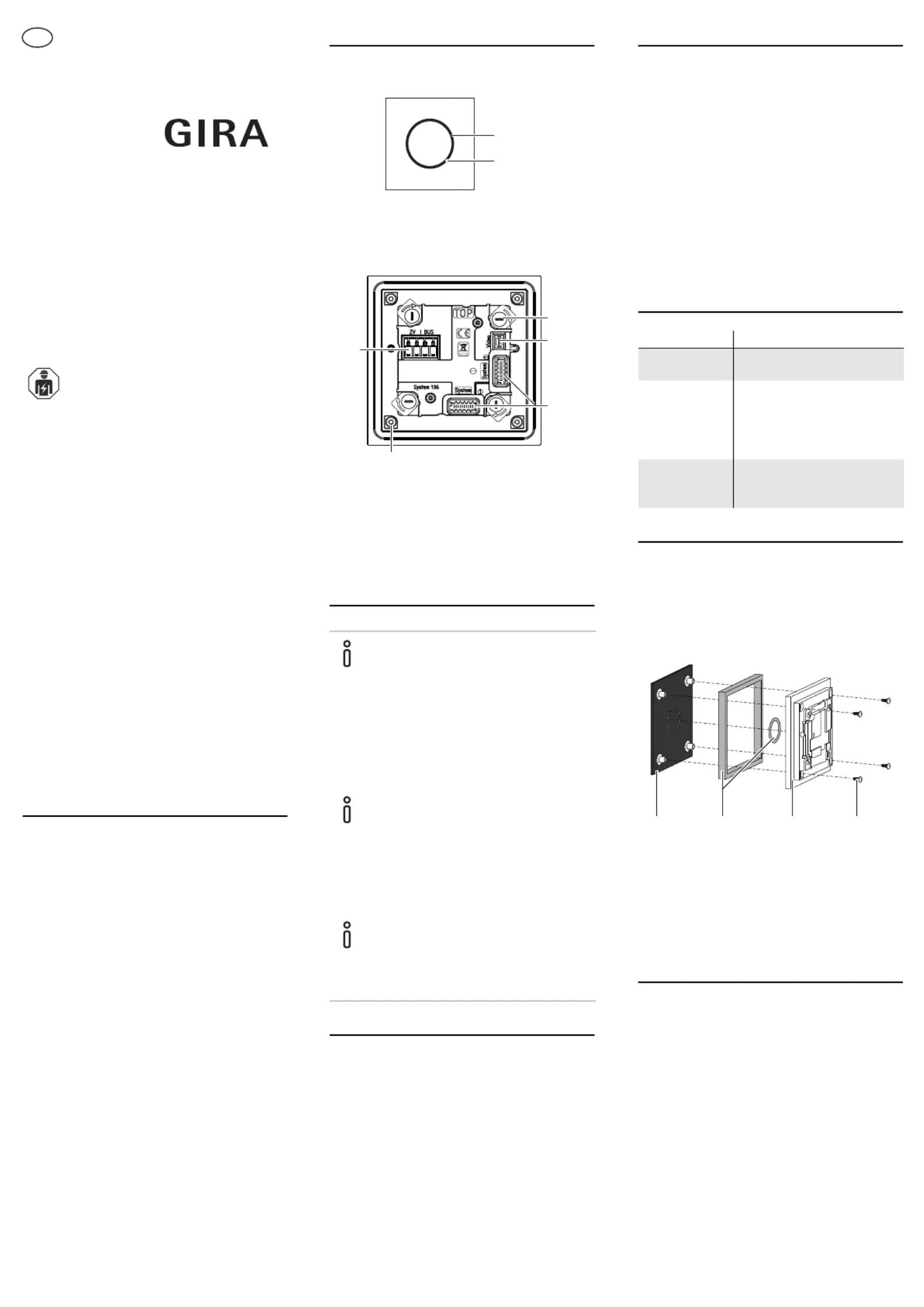
Device description
Front view
Rear view
Installing the module
Start-up of the module
The intercom module can only be started up
via the control device when connected to a
call-button module (see installation and
operating instructions of the control device).
For a successful start-up, all other devices
(System 106 modules, home stations,
control device, etc.) must have been
previouslyinstalled.
1Microphone and loudspeaker aperture
2Status LED
1Turn-type lock (4 x)
2Slot: video
3Slot (2 x): System cable
4Mounting (4 x): Module front
5Plug terminal: Power supply (BUS) and
additional supply (ZV)
Installing the module
The following work steps can be found in
the installation instructions for the
System 106 surface-mounted housing, 1-
gang to 5-gang:
•Lock module on function carrier.
•
Connect cable.system
•
Connectterminating resistances.
Terminating resistance
Two terminating resistances are included
from surface-mounted housing, 2-gang.
The terminating resistances are always
attached to the first and last module on the
system cable.
Installation position of plug termi-
nal
Observe the correct installation position
(reversed) for the plug terminal.
1
2
2
3
4
1
5
Configuring the module
Volume control
The volume is controlled at the call-button
module (see call-button module operating
instructions).
Switching acoustic call-button actua-
tion on or off
Acoustic call-button actuation is switched
on or off at the call-button module (see
operating instructions for call-button
module).
All acknowledgement tones continue to
sound in activated programming mode.
Status LED
Changing the module front
1.Open housing and remove the function
carrier.
2.Unlock intercom module and remove
from function carrier.
3.Remove mounting screws and then
remove the module front including seals.
4.Position new module front with new
seals and assemble in reverse order.
Technical data
LEDMeaning
Flashes
orange
Programming mode active
Lights up red
continuously
Failure of additional
supply, system bus short
circuit or low voltage or
voltage of additional
supply > 30 V
Flashes green
for short
period of time
Acknowledgement when
button is pressed
1Module front
2Seals
3System 106 intercom module
4Mounting screws (4 x)
Power supply:via control device
or via additional
power supply
(DC 24 V 300 mA)
Voice connection power
consumption:approx. 1.0 W
Stand-by mode:200 mW
Connections:2 x 2-wire bus
2 x additional
supply
2 x system
1 x video
Ambient temperature:-25 °C to +70 °C
Protection typeIP54
Dimensions (W x H):106.5 x 106.5 mm
1324
10864529 40/16
System 106
Intercom module
5563 9..
Operating instructions
en
Produktspecifikationer
| Varumärke: | Gira |
| Kategori: | Intercomsystem |
| Modell: | System 106 |
| Bredd: | 106.5 mm |
| Höjd: | 106.5 mm |
| Antal knappar: | 1 |
| Produktens färg: | Rostfritt stål |
| Strömförsörjning via Ethernet (PoE) stöd: | Nej |
| Temperatur vid drift: | -25 - 70 ° C |
| Internationellt skydd (IP) kod: | IP54 |
| Tangentbordsbelysning: | Ja |
| Material, hölje: | Rostfritt stål |
| Anslutningsteknologi: | Kabel |
| Högtalartelefon: | Ja |
| Utomhusenhet ingår: | Ja |
| Spänningsenhet utomhusenhet: | AC/DC |
| Anslutningstyp: | 10-polig kontakt |
| Inomhusenhet ingår: | Nej |
| Moduler kvantitet (max): | 1 modul/-er |
Behöver du hjälp?
Om du behöver hjälp med Gira System 106 ställ en fråga nedan och andra användare kommer att svara dig
Intercomsystem Gira Manualer

20 September 2024
28 Augusti 2024
23 Augusti 2024
20 Augusti 2024
19 Augusti 2024
19 Augusti 2024
17 Augusti 2024
17 Augusti 2024
13 Augusti 2024
9 Augusti 2024
Intercomsystem Manualer
Nyaste Intercomsystem Manualer
28 Mars 2025
27 Mars 2025
27 Mars 2025
27 Mars 2025
27 Mars 2025
11 Mars 2025
10 Mars 2025
9 Mars 2025
2 Mars 2025
20 Februari 2025