Kramer SI-1VGA Bruksanvisning
Kramer Kontroller SI-1VGA
Läs gratis den bruksanvisning för Kramer SI-1VGA (2 sidor) i kategorin Kontroller. Guiden har ansetts hjälpsam av 27 personer och har ett genomsnittsbetyg på 4.1 stjärnor baserat på 9 recensioner. Har du en fråga om Kramer SI-1VGA eller vill du ställa frågor till andra användare av produkten? Ställ en fråga
Sida 1/2
The Kramer SI1VGA- - Stepin Module
Congratulations on purchasing your Kramer SI-1VGA Step-in Modulewhich is ideal for
boardrooms and presentation rooms.
The Kramer VGA and unbalanced stereo audio remoteSI-1VGA is a control panel that
can, for example, the Kramer fit into TBUS-10 Table ConnectionBox (see
Figure 3) or
the The K-POD301. Podium Table BusSI-1VGA is used for remotely taking control of
a compatible switcher, for example, the VP-81KSi.
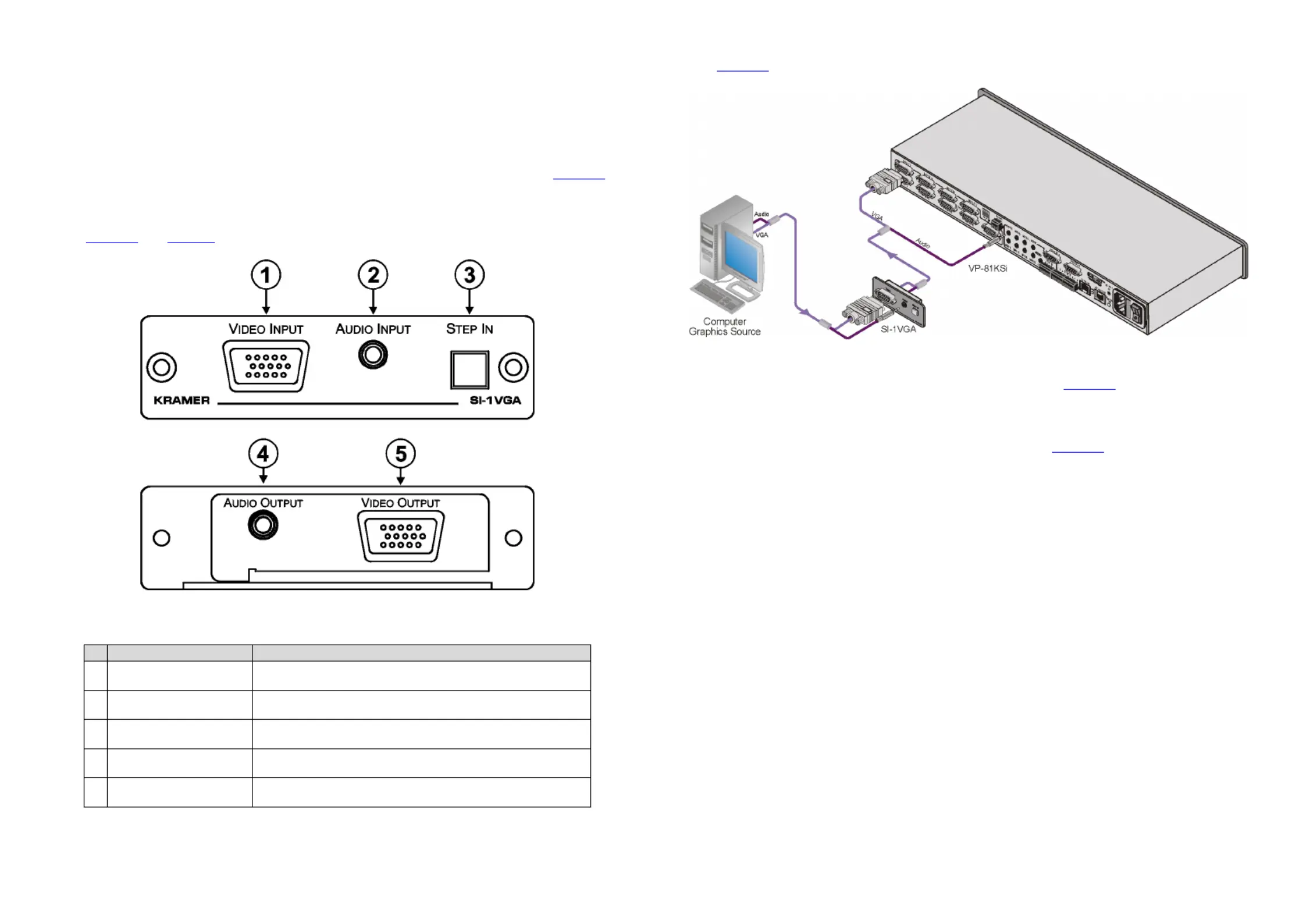
Figure 1 and Table 1 define the SI- 1VGAStep-in Module.
Figure SIFront Panel 1: - -1VGAStepin Module and Rear View
Table SI1: - -1VGAStepin Module Front and Rear Features
# FeatureFunction
1 VIDEO INPUTVGA 15-pin HD
(F) Connector
Connect to video sourcethe
2 AUDIO INPUT3.5mm Mini
Jack
Connect to nced stereo audio source the unbala
3 STEPINButton Press to switch the input to this remote control panel. LED lights yellow
when active
4 AUDIOOUTPUT 3.5mm Mini
Jack
Connect to unbalanced stereo audio inputthe of the switcher
5 VIDEO OUTPUT VGA 15-pin
HD (F) Connector
Connect to video inputthe of the switcher. (The cable used must connect
all pins, for example, Kramer cable CP-GMA/GMA/XL)
Figure 2 shows the wiring connections of the SI-1VGA.
Figure SI2: - 1VGAWiring Connections
To install as illustrated in and connect the SI- 1VGAFigure 2:
Note: Theeps assume that you have video (with 15 tfollowing s-pin HD (M)
connectors) and audio (with 3.5mm mini jacks) cables running from the switcher
inputs to the inside of either the TBUS-10 (see
Figure 3) or the
K-POD301, depending on which you are using.
1. Connect the video cable in the TBUS-/K-10POD301-to the 15pin HD VIDEO
OUTPUT connector on the rear of the SI-1VGA.
2. Connect the audio cable in the TBUS-/K-10POD301 to the 3.5mm minijack
AUDIO OUTPUT connector on the rear of the SI-1VGA.
3. . InserttheSI-1VGAinto the required cutout of theTBUS--10/KPOD301
4. Insert the two screws to secure the module in place and tighten the screws.
5. Plug the video source (for example, a computer) into the 15-pin HD VIDEO
INPUT connector on the front panel ofthe SI-.1VGA
6. Plug the audio source (for example, a computer) into the 3.5mm mini jack AUDIO
INPUT connector on the front panel of SI-1VGA.
7. . Press the STEP IN button to take control of the switcher input
Produktspecifikationer
| Varumärke: | Kramer |
| Kategori: | Kontroller |
| Modell: | SI-1VGA |
Behöver du hjälp?
Om du behöver hjälp med Kramer SI-1VGA ställ en fråga nedan och andra användare kommer att svara dig
Kontroller Kramer Manualer

7 Juli 2025
10 September 2024
10 September 2024
8 September 2024
8 September 2024
8 September 2024
8 September 2024
7 September 2024
7 September 2024
6 September 2024
Kontroller Manualer
Nyaste Kontroller Manualer
2 April 2026
1 April 2026
28 Mars 2026
15 Mars 2026
14 Mars 2026
1 Mars 2026
19 Februari 2026
6 Februari 2026