Lowrance LCX-20C Bruksanvisning
Lowrance Inte kategoriserad LCX-20C
Läs gratis den bruksanvisning för Lowrance LCX-20C (200 sidor) i kategorin Inte kategoriserad. Guiden har ansetts hjälpsam av 45 personer och har ett genomsnittsbetyg på 4.0 stjärnor baserat på 3 recensioner. Har du en fråga om Lowrance LCX-20C eller vill du ställa frågor till andra användare av produkten? Ställ en fråga
Sida 1/200
Pub. 988-0151-261
www.lowrance.com
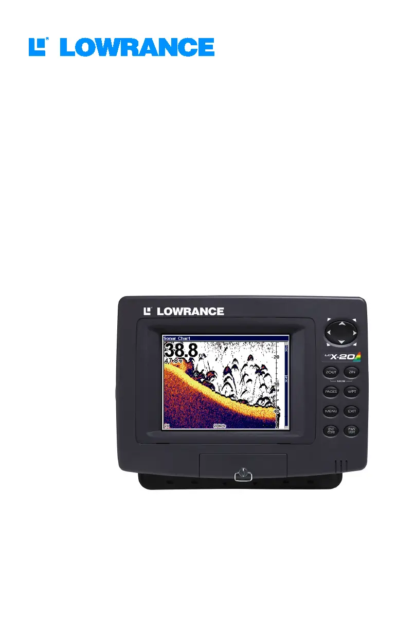
LCX-20C
Fish-finding Sonar & Mapping GPS
Operation Instructions
Produktspecifikationer
| Varumärke: | Lowrance |
| Kategori: | Inte kategoriserad |
| Modell: | LCX-20C |
Behöver du hjälp?
Om du behöver hjälp med Lowrance LCX-20C ställ en fråga nedan och andra användare kommer att svara dig
Inte kategoriserad Lowrance Manualer

5 Oktober 2024
30 September 2024
25 September 2024
12 September 2024
1 September 2024
31 Augusti 2024
30 Augusti 2024
29 Augusti 2024
24 Augusti 2024
24 Augusti 2024
Inte kategoriserad Manualer
Nyaste Inte kategoriserad Manualer
9 April 2025
9 April 2025
9 April 2025
9 April 2025
9 April 2025
9 April 2025
9 April 2025
9 April 2025
9 April 2025
9 April 2025