MGL Avionics Vega Control Bruksanvisning

Läs nedan 📖 manual på svenska för MGL Avionics Vega Control (37 sidor) i kategorin Inte kategoriserad. Denna guide var användbar för 24 personer och betygsatt med 4.5 stjärnor i genomsnitt av 2 användare

Sida 1/37
MGL Avionics
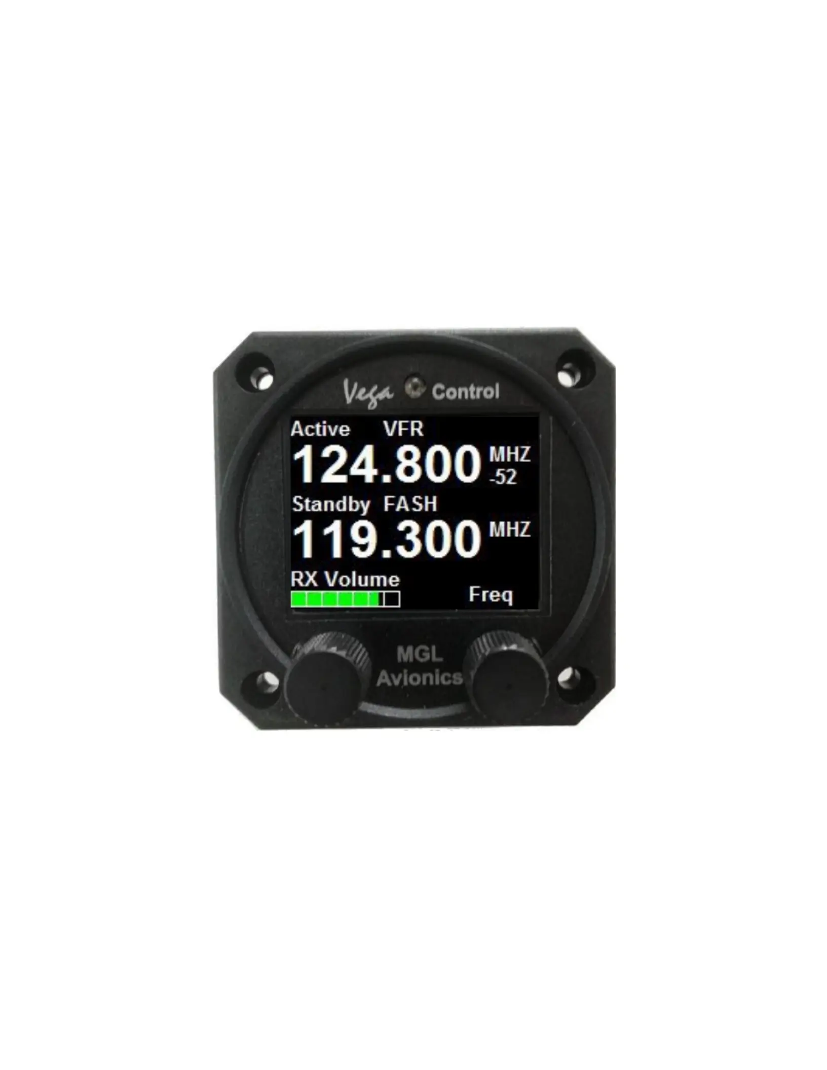
Vega 2.1/4” control head
for V16 aviation band transceiver
and N16 VHF navigation receiver
User and Installation manual
Page 1
Table of Contents
General........................................................................................................................................4
Document history........................................................................................................................4
Description..................................................................................................................................4
Multiple control heads.................................................................................................................4
Interface with MGL EFIS systems...............................................................................................4
Interface with non-MGL EFIS systems.......................................................................................5
Multiple V16/N16 systems...........................................................................................................5
Vega modes of operation............................................................................................................6
COM .......................................................................................................................................6
Primary NAV............................................................................................................................6
Secondary NAV.......................................................................................................................6
NAV ALL..................................................................................................................................6
V16 COM radio interface – operation.........................................................................................7
Rotary controls........................................................................................................................7
Ambient light sensor...............................................................................................................7
Main display - receive.................................................................................................................8
Main display - transmit................................................................................................................9
Messages....................................................................................................................................9
STUCK PTT !!!..................................................................................................................10
V16 FAULT.......................................................................................................................10
Antenna !..........................................................................................................................10
Adjusting volumes and squelch.................................................................................................11
Adjust RX Volume.................................................................................................................11
Adjust RX Squelch................................................................................................................11
Adjust Intercom volume.........................................................................................................11
Entering a new standby frequenc.............................................................................................12
Using the rotary control.........................................................................................................12
Rotary control special functions................................................................................................13
Using channels.....................................................................................................................14
Selecting from channel lists..................................................................................................14
External NAV frequency lists................................................................................................14
N16 navigation radio interface – operation...............................................................................15
Typical navigation displays...............................................................................................16
Vega in primary or secondary NAV display mode................................................................17
Adjusting N16 RX volume and RX squelch......................................................................17
Localizer backcourse........................................................................................................17
Using two Vega controls for primary and secondary NAV....................................................18
The NAVCOM mode.........................................................................................................18
The audio output...............................................................................................................18
The morse station decoder...............................................................................................19
Channel identification by text...........................................................................................20
The Menu..................................................................................................................................21
COM mode menu..................................................................................................................21
NAV mode menu...................................................................................................................21
Page 2
COM or NAV Setup Menu.....................................................................................................22
Head Setup Menu.................................................................................................................22
Edit channels....................................................................................................................22
Head Type........................................................................................................................22
No TX Info/Show TX info..................................................................................................23
Backlight...........................................................................................................................23
Emulation..........................................................................................................................23
Channel Spacing..............................................................................................................23
Input setup........................................................................................................................23
About................................................................................................................................24
Rotary rollover/clamp........................................................................................................24
Check …...........................................................................................................................24
Vega head firmware..................................................................................................................24
Editing channel memory............................................................................................................26
Environmental qualification matrix............................................................................................27
Typical connection diagrams.....................................................................................................29
Remote control..........................................................................................................................30
Pinout for 3.18” Razor and 2.25” Vega transceiver control head.........................................31
Specifications............................................................................................................................32
Dimensions................................................................................................................................33
Garmin protocol limitations.......................................................................................................34
Example Harness schematic....................................................................................................35
NAVCOM device using V16 and N16.......................................................................................36
Using audio transformer on the AUX input...............................................................................37
Page 3
General
This manual documents the installation and use of the MGL Avionics Vega NAV/COM 2.1/4”
control head.
The Vega NAV/COM control head is designed to interface to a MGL Avionics V16 VHF
airband transceiver or a MGL Avionics N16 VHF Navigation receiver.
Document history
28 February 2018, first release
Description
The Vega control head consists of a body designed to fit a standard 2.1/4” instrument cutout.
The Vega is designed for panel front or rear mounting.
The Vega features a 1.8” color TFT screen. Two Rotary controls are provided. Display light
intensity may be adjusted to fixed values or set automatically based on ambient light levels
measured by a sensor above the display.
The Vega interfaces to a V16 and or N16 using a two wire CAN bus. Two RS232 ports are
provided. RS232 port 1 may be used as interface to third party systems implementing industry
standard communication protocols. The same port may also be used to upload firmware
updates to the Vega using a PC application provided by MGL Avionics. RS232 port 2 is
reserved for special applications and is not currently used.
Two analog voltage inputs are provided. Input one may be used together with a switch to
implement a stick mounted last reception recall for the V16 transceiver.
Input two may be used to implement a selection of one, two or three button frequency or
channel selection switches.
Multiple control heads
There are no limitations to the number of control heads installed in parallel.
Control head types can be mixed, for example you may mix Razor 3.1/8” heads with Vega
2.14” heads. Heads require no specific configuration for multiple head operation. Simply
connect them in parallel on the CAN bus.
Interface with MGL EFIS systems
Heads are not connected in any way to a MGL Avionics EFIS system.
Should you wish to operate an MGL EFIS with a V16 and/or N16, the MGL EFIS connects
directly to the V16 via an EFIS RS232 port. In case of a V16 and N16 combination, the N16 is
connected to the V16 via CAN bus and the V16 RS232 port provides both V16 and N16 data
to the EFIS. In case of a single N16 receiver, connect the RS232 port 1 of the N16 to the
Page 4
RS232 port of the EFIS.
Note that the CAN bus between heads, V16 and N16 is a private CAN bus. It must not be
connected to an EFIS CAN bus or any other can bus in your aircraft.
You may operate heads and EFIS connection at the same time.
Interface with non-MGL EFIS systems
Using any Razor or Vega head, RS232 port 1 implements a industry standard, Garmin
compatible protocol. As there are several protocol types please select the desired variant in
the head setup menu.
Note: If you have both V16 and N16 connected via CAN bus to your head, you can select a
NAV/COM protocol such as SL30 or GNC255. If you have only a V16 connected, select one
of the COM protocols such as SL40, GTR200, GTR225.
It is possible to connect only a N16. In this case select a NAV/COM protocol. The protocol will
include the COM parts but these will not be functional – for example if you were to set a COM
frequency this will not work and the head will return a fixed frequency set to 118.000Mhz.
The protocols are implemented fully including various forms of frequency lists and tables
depending on the chosen protocol which can be used with compatible GPS receivers. Note:
Generally, EFIS systems do not download frequency lists but set individual frequencies from
their databases.
Multiple V16/N16 systems
Should you wish to use multiple V16 and/or N16 systems, please wire each system with a
separate CAN bus.
Page 5
Vega modes of operation
The Vega can be selected to operate in one of four modes:
COM
In this mode the Vega acts as control for a V16 COM transceiver.
Primary NAV
In this mode the Vega acts as control for a N16 NAV receiver primary frequency. It can be
used as VOR or ILS control and display depending on the tuned primary navigation
frequency. Frequency settings from the Vega will change the primary frequency directly.
This mode is normally only used if a second Vega is used for the secondary frequency,
however should you not want to use the secondary frequency it is acceptable to use the Vega
in this mode.
Secondary NAV
In this mode the Vega acts as control for a N16 NAV receiver secondary frequency. It can be
used as VOR or ILS control and display depending on the tuned secondary navigation
frequency. Note: The secondary frequency is only active with the N16 placed in SCAN mode.
If the N16 is not in SCAN mode the displayed VOR or ILS will be shown in gray colors and will
not be functional.
This mode is only used if a second Vega is set to Primary NAV mode.
NAV ALL
Using this mode the Vega acts as both primary and secondary navigation frequency controls
and display for a N16 navigation receiver. All frequency settings are sent to the secondary
frequency. Primary and secondary frequencies can be flipped.
Page 6
V16 COM radio interface – operation
Rotary controls
The rotary control on the left is used to set the RX volume. Pushing the control enters the
menu. In menu mode rotating the control selects the menu item. Pushing the control while in
menu mode exits the menu or selected sub menu.
The right rotary control is used to enter a new standby frequency, flip active and standby
frequency, switch scanning on and off and select the 121.5Mhz emergency channel. The
Rotary control is also used to select from preset channel lists and is also used for many of the
menu and setup functions. Generally, when in any menu mode this rotary control adjusts the
value of the selected item. In channel mode, this control selects the channel.
Ambient light sensor
The display brightness can be adjusted either in fixed steps (using the menu) or it can be set
to automatically adjust depending on the amount of ambient light measured at the sensor.
Page 7
Right rotary control
with push down
button
Ambient light
sensor
Left rotary control
with push down
button
Main display - receive
Notes: Frequency display flashes when signal received above squelch level. Signal strength
readout in dbm only visible when signal above squelch level.
Internal channel storage can be edited via the Menu -> head setup.
Further channel storage options available via downloaded channel lists from external
equipment depending on protocols selected and availability of such functionality on external
equipment such as EFIS systems.
Playback feature: The V16 can playback the last received transmissions. This can be
activated by wiring a switch to the Vega or V16. Please refer to the V16 manual if you would
like to wire this switch to the V16. For the Vega, please view this manual with respect to the
A1 and A2 inputs and selected menu function related to these inputs.
Channel based frequency selection may be operated via remote switches. This can be
configured to operate in various modes and number of switches. Please view the options in
the Vega A1/A2 menu.
You can also enter channel select mode by pushing the right rotary control and while pressing
it turning the knob. You can then select between direct frequency entry, internal channel
storage or, if available, any downloaded frequency list.
Page 8
The active
Frequency.
This is used for TX
As well as RX
RX volume
Level.
Adjust with
Rotary control
Text related to frequency
From channel storage
Current receive
Signal level in dbm
Standby frequency,
Monitored if scanning
Active.
Adjust standby frequency
Or select channel if in channel
Mode using rotary control
Main display - transmit
Notes: TX power and VSWR are only shown during TX if "Show TX Info" is selected in Menu
-> Head. If not selected, the standby frequency will be shown in this field.
Current modulation is derived from actual demodulation of the outgoing TX carrier wave and
is a true reflection of modulation of the carrier.
Transmit power is a true RF forward power measurement using a directional coupler at the
antenna connector. Typical readings are around 10W (or 5W if low power TX mode selected).
Power readings can vary depending on tuned frequency, antenna match at that frequency,
internal temperature of the transmitter (if exceeding high levels) or power supply voltage if
below 13.8V DC during transmit.
VSWR reading is taken from a directional coupler at the antenna connector which looks into
the transmitter harmonics filter as termination. Due to variable impedance at this location the
VSWR reading may differ slightly from that of a similar meter inserted at the antenna but
nevertheless is a good indication of antenna match. A good antenna match would give
readings below 1.5 at any frequency. Readings above 2.0 should be investigated and may
indicate a badly tuned or unsuitable antenna. Transmitting into a 50 ohm RF dummy load
produces a perfect match and a reading of 1.0.
Messages
The following messages may be displayed:
Page 9
Active frequency
Currently transmitting
Current modulation
Of TX carrier. Visual
Check of actual TX signal.
Current antenna match
Expressed as
Voltage standing wave
Ratio (VSWR)
Current
Average transmit
Power (carrier
Power) expressed
In Watts
STUCK PTT !!!
This displays when transmission has been active for 35 seconds. The V16 conforms to the
requirements of DO-207. After 35 seconds the V16 reverts back to receive mode even if the
PTT remains active. Releasing PTT resets the 35 second timer and a new transmission may
commence.
V16 FAULT
This displays if the internal self diagnostics of the V16 transceiver has detected an internal
fault that may cause incorrect operation. Please make arrangements to have your V16
transceiver checked and if required, repaired by a qualified service lab.
Antenna !
This message will be displayed in case of a very bad antenna match during transmit. If this
message appears transmit power will have been reduced automatically to prevent destruction
of the transmitter.
Please check your antenna and antenna cable as well as connectors for shorts or open
circuits. If this happens with an antenna that was previously operating fine, check connectivity
to the antenna ground plane and check for corrosion.
For new installations, please ensure that your antenna has a properly configured ground
plane of sufficient size.
Page 10

Produktspecifikationer

Varumärke: MGL Avionics
Kategori: Inte kategoriserad
Modell: Vega Control
Färg på produkten: Wit
AC-ingångsspänning: 230-400 V
AC-ingångsfrekvens: 50 - 60 Hz
Antal moduler: 1

Behöver du hjälp?

Om du behöver hjälp med MGL Avionics Vega Control ställ en fråga nedan och andra användare kommer att svara dig


Inte kategoriserad MGL Avionics Manualer

Inte kategoriserad Manualer

Nyaste Inte kategoriserad Manualer