Optex OVS-01GT Bruksanvisning
Läs gratis den bruksanvisning för Optex OVS-01GT (1 sidor) i kategorin Detektor. Guiden har ansetts hjälpsam av 22 personer och har ett genomsnittsbetyg på 4.1 stjärnor baserat på 8 recensioner. Har du en fråga om Optex OVS-01GT eller vill du ställa frågor till andra användare av produkten? Ställ en fråga
Sida 1/1
Microwave Range
Sensor Mode
Calibration
Output Logic
N.O.
N.C.
2.5m
8’
3m
10’
3.5m
11.5’
4m
13’
4.5m
15’
5m
16’
5.5m
18’
2m
7’
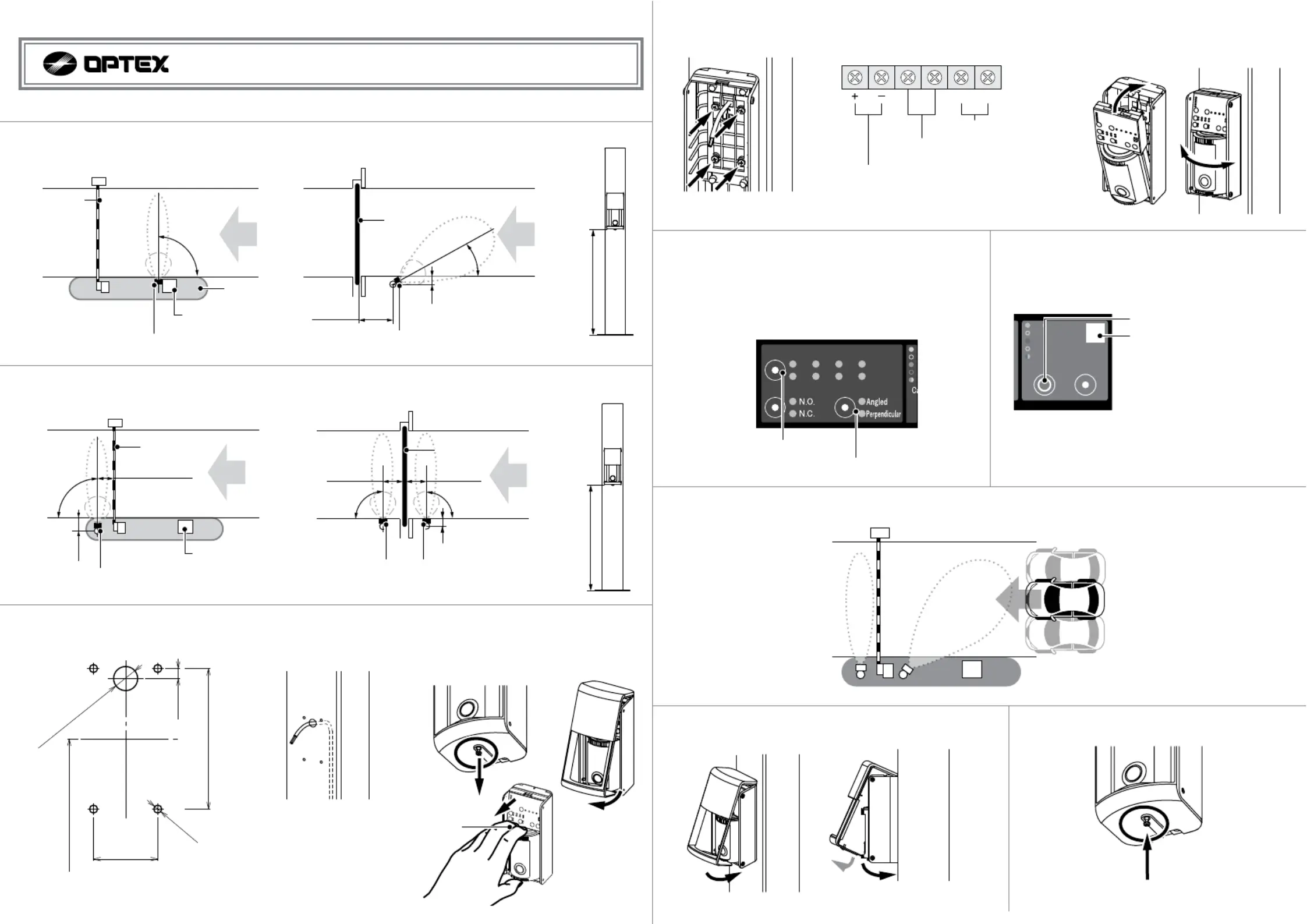
OVS-01GT(E) Quick Reference Guide
1. If used for Activation, go to section 2. If used for Vehicle protection, go to section 3.
2. If Activation function, find the installation location by referring the following chart.
Installation height has to be 500mm(20”) from the ground.
3. If Vehicle protection function, find the installation location by referring the following chart. Always recommended to install
700mm(71”
) far from barrier or slide gate. Installation height has to be 500mm(20”) from the ground.
[1] Make holes to mount the sensor.
[2] Run a cable thru the post or pole.
[4] Mount the base using 4 screws.
[5] Connect wires.
Pr Soweupply 12-24V
DC
Non-Volte y Output N N.CagRela.O. /. Switchable
30VDC 0.3A or less siste d)(reancloa
Applicable Wire
Solid wire: 0.4-1.6mm (AWG 26-14)
Stranded wire: 0.13-2.0sq (AWG 26-14)
SignalGND
Iunpt Active High / w SwitleLochab
Prowe OutpuIt nput
5.
Sethe Micave t row
e d Ssor e aranganenmods fws:ollo
Angled : 5m(16’)
Perpendicular : 3.5m(11.5’) (factory default setting)
Usually, other settings can be default settings.
For detailed settings, refer to Advance Installation on page 17.
6. Perform sensor calibration in order to memorize the
background of the detection area. Ensure no
pedestrians or vehicles are present.
CionAreheckalratiba C
Stadby
Area Check
Dectteion
Calirabtion
Calirabtion Error
1. Press the Calibration button.
2. Operation indicator blinks in blue.
7. System operation check.
Check the entire coverage area by using actual vehicle.
Left side of the lane
Center of the lane
Right side of the lane
[6] Attach the sensor body to the base
and adjust the sensor angle.
8. Put the fcover t t of t base first, d attach it ront onheophean
while spreading it open and pushing down the front cover.
9. Tighten the front cover retaining screw.
[3] n the retg scs on the bottom Looseaininrew
of the fncov ve the fnt rot erandremoro
cover, detach the sensor unit.
Hold here and
pull forward
Vehicle
Path
Gate Bar
Sensor mode : Perpendicular
Installation Height of 500mm(20in.)
Island
90°
Ticket Vending
Machine
4. Install the sensor, wire it and apply power.
GL+588(23.15)
Mounting
Pitch 32±1
(1.26±0.04)
Mounting Pitch
70±1(2.76±0.04)
5(0.20)
M4 Tap
Depending on the
cable diameter
[Unit : mm(inch)]
Gate
Sensor mode : Angled
Installation Height of 500mm(20in.)
30°
100
mm(4in.)
1100
mm
(43in.)
Secure side
Public side
Vehicle
Path
Gate
90°
100
mm(4in.)
90°
Sensor mode : Perpendicular
Installation Height of 500mm(20in.)
Secure side
Public side
700
mm
(28in.)
700
mm
(28in.)
Vehicle
Path
90°
Gate Bar
150m
m
(6in.)
Island
700
mm(28in.)
Sensor mode : Perpendicular
Installation Height of 500mm(20in.)
Ticket Vending
Machine
Vehicle
Path
500mm(20in.)500mm(20in.)
Barrier GateSlide Gate
Barrier GateSlide Gate
3. Step away from sensor and
outside detection area.
4. Green LED lights when done
correctly.
59-2954-0
Sensor Mode button
Microwave
Range button
Produktspecifikationer
| Varumärke: | Optex |
| Kategori: | Detektor |
| Modell: | OVS-01GT |
Behöver du hjälp?
Om du behöver hjälp med Optex OVS-01GT ställ en fråga nedan och andra användare kommer att svara dig
Detektor Optex Manualer

5 September 2025
4 September 2025
3 September 2025
3 September 2025
19 Juni 2025
21 December 2024
17 September 2024
16 September 2024
30 Augusti 2024
24 Augusti 2024
Detektor Manualer
Nyaste Detektor Manualer
2 April 2026
28 Mars 2026
26 Mars 2026
25 Mars 2026
24 Mars 2026
23 Mars 2026
23 Mars 2026
21 Mars 2026
21 Mars 2026
20 Mars 2026