Peerless-AV DMU50SM Bruksanvisning
Peerless-AV ej kategoriserat DMU50SM
Läs gratis den bruksanvisning för Peerless-AV DMU50SM (2 sidor) i kategorin ej kategoriserat. Guiden har ansetts hjälpsam av 26 personer och har ett genomsnittsbetyg på 4.3 stjärnor baserat på 2 recensioner. Har du en fråga om Peerless-AV DMU50SM eller vill du ställa frågor till andra användare av produkten? Ställ en fråga
Sida 1/2
�
�
�
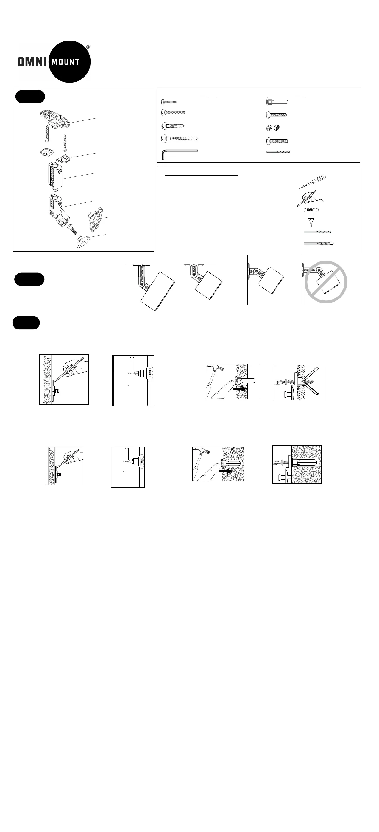
Ceiling
Wall
Wall
Step 1 Identify parts
Additional installation tools
Phillips Head Screw Driver
Pencil
Electric Drill
Drill Bits: 1/8'' drill bit for drywall
5/16'' masonry bit for cement wall applications
Step 3 Installation of the wall plate
Mounting to drywall.
1. Use the wall plate as a template and mark the screw hole locations onto the surface using a pencil.
2. Drill into the drywall with a 1/4'' drill bit. Insert the anchors into the hole as shown in fig. 3.
3. Secure with the #12 x 1-3/4'' screws, see fig. 4.
Mounting to solid concrete or cinder block.
1. Drill into the surface with a 3/16'' masonry drill bit 1-3/4" deep and insert the anchors into the holes as shown in Fig. 3
2. Secure wall plate with the #12 x 1-3/4" , see fig. 4.
1/8”
5/16''mason bit
�
�
These fasteners and tools are provided
3/32''
�
Step 2
Decide on location
�
Extension
Adjusting knuckle
Speaker plate
Mounting plate (1)
Screw covers
Mounting plate (2)
fig. 3
fig. 3
(1) (5) M4 X 12mm Phillips
pan head machine screw
(1) (5) M5 X 12mm Phillips pan
head machine screw
(2) (10) #12 X 3/4" Phillips pan
head self-tapping screw
(2) (10) #12 X 1-3/4'' Phillips pan
head self-tapping screw
(1) (5) 5/32'' Hex key
(2) (10) Plastic anchor
(1) (5) 8-32 X 5/8'' Phillips pan
head machine screw
(1) (5) Circular nut (PEM)
8-32 thread
(1) (5) 1/4-20 X 1" Phillips pan
head machine screw
(1) (2) 3/32'' Drill bit
fig. 4
fig. 4
�
�
�
AB2/AB2 HTS INSTALLATION INSTRUCTIONS
fig.2
�
1 3/4"
fig.2
�
1 3/4"
�
�
�
AB2 HTSAB2 HTS
Knurled side
Produktspecifikationer
| Varumärke: | Peerless-AV |
| Kategori: | ej kategoriserat |
| Modell: | DMU50SM |
Behöver du hjälp?
Om du behöver hjälp med Peerless-AV DMU50SM ställ en fråga nedan och andra användare kommer att svara dig
ej kategoriserat Peerless-AV Manualer

29 September 2025
13 September 2025
13 September 2025
13 September 2025
13 September 2025
13 September 2025
13 September 2025
13 September 2025
13 September 2025
13 September 2025
ej kategoriserat Manualer
Nyaste ej kategoriserat Manualer
3 April 2026
3 April 2026
3 April 2026
3 April 2026
3 April 2026
3 April 2026
3 April 2026
3 April 2026
3 April 2026