Prestige APSSECRS Bruksanvisning
Prestige
ej kategoriserat
APSSECRS
Läs gratis den bruksanvisning för Prestige APSSECRS (33 sidor) i kategorin ej kategoriserat. Guiden har ansetts hjälpsam av 21 personer och har ett genomsnittsbetyg på 5.0 stjärnor baserat på 11 recensioner. Har du en fråga om Prestige APSSECRS eller vill du ställa frågor till andra användare av produkten? Ställ en fråga
Sida 1/33

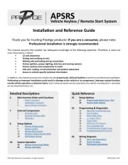
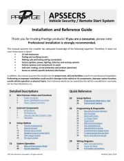
Installaon and Reference Guide
2020 Voxx Electronics Corporaon. All rights reserved. APSSECRS_RevD_07/20
2 Wire Harness Colors and Funcons
2 Power Connector
3 Alarm / Nocaon Connector
4 Input / Output Connector
7 External Components
7 Shock Sensor
7 RF Antenna Kit
7 Data Bus Interface (FLCART / DBI)
7 Telemacs
8 Setup Opons
8 Remote Programming
9 Security Control
13 Remote Start Control
17 Negave Output Control (NOC)
19 AUX Output Control
20 PIC Input Control
21 System Operaon
21 Manual Transmission Mode
22 Remote Operaon
APSSECRS
Vehicle Security / Remote Start System
23 Setup Opons
23 Programming Mode Entry / Exit
24 Feature Bank Opons
25 Programming & Diagnoscs
25 Data Port Protocol Selecon
25 Tach Funcon
25 Dome Light Delay
26 2 / 4 Hour Timer
26 Turbo Timer
26 Silent Arm and Disarm
27 User Selectable LED
27 Adjusng Shock Sensor
27 Troubleshoong Trigger Zones
27 Troubleshoong Remote Start
28 Alarm Override Procedures
29 Wiring Diagrams
29 Door Lock Connecons
32 Starter Kill Relay
33 Full System Connecons
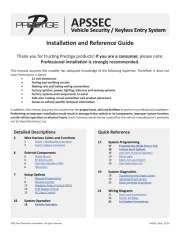
Thank you for trusng Presge products! If you are a consumer, please note:
Professional installaon is strongly recommended.
This manual assumes the installer has adequate knowledge of the following experse. Therefore, it does not
cover these topics in detail:
• 12-volt electronics
• Tesng and verifying circuits
• Making safe and lasng wiring connecons
• Factory ignion, power, lighng, data bus and sensing systems
• Factory systems and components to avoid
• Safe wire roung, circuit protecon and product placement
• Access to vehicle-specic technical informaon
In addion, this manual assumes the installer has the proper tools, skill and facilies to perform a professional installaon.
Performing an improper installaon could result in damage to the vehicle or its components, improper system funcon,
unsafe vehicle operaon or physical injury. Such instances would not be covered by the vehicle manufacturer's warranty,
nor by Voxx Electronics, Inc.
Detailed Descripons Quick Reference
Produktspecifikationer
| Varumärke: | Prestige |
| Kategori: | ej kategoriserat |
| Modell: | APSSECRS |
Behöver du hjälp?
Om du behöver hjälp med Prestige APSSECRS ställ en fråga nedan och andra användare kommer att svara dig
ej kategoriserat Prestige Manualer
4 Augusti 2025
4 Augusti 2025
4 Augusti 2025
ej kategoriserat Manualer
- Jolin
- Monacor
- Alpina
- IK Multimedia
- XP-PEN
- Inkbird
- Cien BEAUTY
- Irradio
- Elation
- Thermalright
- VALOI
- SmallRig
- Carson
- Heatfab
- Eico
Nyaste ej kategoriserat Manualer
23 Oktober 2025
23 Oktober 2025
23 Oktober 2025
23 Oktober 2025
23 Oktober 2025

23 Oktober 2025

23 Oktober 2025
23 Oktober 2025
23 Oktober 2025
23 Oktober 2025