Scanstrut SC-V-P1 Bruksanvisning
Scanstrut ej kategoriserat SC-V-P1
Läs gratis den bruksanvisning för Scanstrut SC-V-P1 (2 sidor) i kategorin ej kategoriserat. Guiden har ansetts hjälpsam av 31 personer och har ett genomsnittsbetyg på 4.6 stjärnor baserat på 8 recensioner. Har du en fråga om Scanstrut SC-V-P1 eller vill du ställa frågor till andra användare av produkten? Ställ en fråga
Sida 1/2
EN READ THESE INSTRUCTIONS BEFORE INSTALLING THE PRODUCT
ESLEA ESTAS INSTRUCCIONES ANTES DE INSTALAR EL PRODUCTO
FR-CALIRE CES INSTRUCTIONS AVANT D’INSTALLER LE PRODUIT
scanstrut.com
Ventura Series
Dual 125V 20A AC Outlet
Electrical Information
& Installation Instructions
SC-V-P1
UK / EMEA / APAC
Scanstrut Ltd, 14 Dart Business Park,
Clyst St. George, Exeter, EX3 0QH
USA
Scanstrut Inc. 7 Pequot Park Rd,
#303 Westbrook, CT 06498
RevA OEM-INST005766
For the latest tech info visit
scanstrut.com
Technical Information
Rating20A 125V
Cable
12AWG Triplex Recommended
Copper cable must be used for installation
Receptacle
• Grounded duplex NEMA 5-20R - UL & CSA-listed
• Screw terminals
• Replace receptacle only with Scanstrut part
number SC-UTIL-P-006285 (Qualtek 740W-F/06)
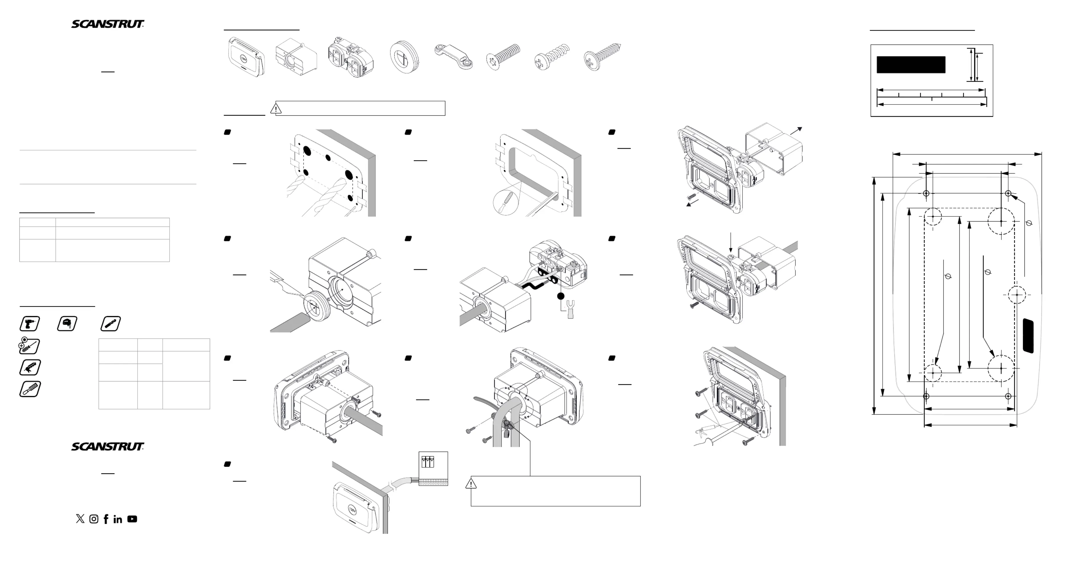
1 x Rear Housing1 x Front Housing
Parts List
1 x Rubber Grommet1 x Receptacle1 x Torx Bolt
1 x Cable Strain
Relief Bracket
4 x No. 6 Flange Screws
5 x 3mm Screws
Drill
Jigsaw
Drill Bit
ø 2.5mm (3/32”) | ø 8mm (5/16”) | ø 12.5mm (1/2”)
Tools Required
Silicone or
Automotive Sealant
Screwdrivers
PH1 | PH2 | T15
Material
Pilot Drill
Size
Fixing
Soft Material
eg. plywood
2.5mm
(3/32”)
Included
4x No.6 Screws
Hard Material
eg. fiberglass,
hardwood, acrylic
3mm
(1/8”)
Metal eg. steel,
aluminium
4mm
(5/32”)
Recommended
Flanged M4 Panhead
Bolts, Washers and
Nyloc Nuts
(Not included)
Drilling Template Scale 1:1
• Cut out template
• Tape to mounting surface
• Use template to drill:
4x ø2.5mm (3/32”) holes
3x ø8mm (5/16”) holes
2x ø12.5mm (1/2”) holes
1
Installation
• Jigsaw inside of the cutting boundary.
DO NOT exceed boundary area.
• Test fit the product - if needed, file the cut
area until a tight fit is achieved.
• Clean mounting surface.
2
• Remove receptacle
(1x Torx T15 bolt)
from front lid assembly.
3
• Fit grommet to rear housing.
• Cut grommet cross hairs to required size
for chosen installation cable.
• Slide length of installation cable
through grommet - cable must
not be connected to
live power source.
4
• Strip wires as required to suitable length
(minimum 7mm (0.28”), then connect and
secure to receptacle terminals:
• Green Ground wire - green screw
• White Neutral wire - silver screws
• Black Hot/Line wire - gold screws
5
• Pull through the mounting
surface and fix the wired
receptacle to the front
housing with the
Torx T15 screw.
• Ensure the ground terminal
is orientated correctly.
6
• Slide rear housing over wired
receptacle.
• Secure to housing assembly
with 3x 3mm PH1 screws.
7
• Apply silicone/automotive sealant to the
4x No.6 PH2 flanged mounting screws.
• Secure the housing assembly to the
mounting surface - DO NOT over tighten
the screws.
8
• Choose the desired installation
cable rear exit orientation.
• Place the cable strain-relief
bracket over the protruding
cable sheath.
• Clamp cable to the rear
housing with the 2x
remaining 3mm PH1 screws.
9
• Professional electrician installation only for
connecting receptacle wiring to onboard 125V system.
• Connect to a breaker (GFCI recommended).
10
File
If daisy chaining connection to multiple
receptacles, the slot features in the
strain-relief bracket can be used to
secure an additional cable to it with a
suitably sized cable tie (not included).
4x
2.5mm (3/32")
2x
12.5mm (1/2")
3x
8.0mm (5/16")
72.5mm (2.85")
68.2mm (2.69")
94.0mm (3.70")
38.0mm (1.50")
31.7mm (1.25")
80.5mm (3.17")
41.8mm (1.65")
43.0mm (1.69")
110.0mm (4.33")
69.0mm (2.72")
50mm
2”
�5mm
0.5”
WARNING:
CHECK SCALE
1
2
3
WH
BK
GN
OR
This product must be mounted strictly in accordance with the provided mounting template
and must not be installed in any location where submersion or partial submersion may occur.
TOP ^
• Only daisy chain to circuit with other 20A duplex receptacles. Do not connect to 15A circuit.
• If daisy chaining to multiple 20A receptacles in a circuit, utilize appropriate wire gauge cable
size per Industry Standards.
• If daisy chaining to multiple 20A receptacles, the first receptacle in the circuit must be
GFCI protected.
Produktspecifikationer
| Varumärke: | Scanstrut |
| Kategori: | ej kategoriserat |
| Modell: | SC-V-P1 |
Behöver du hjälp?
Om du behöver hjälp med Scanstrut SC-V-P1 ställ en fråga nedan och andra användare kommer att svara dig
ej kategoriserat Scanstrut Manualer

31 Augusti 2025
31 Augusti 2025
31 Augusti 2025
31 Augusti 2025
31 Augusti 2025
31 Augusti 2025
31 Augusti 2025
28 Augusti 2025
14 Augusti 2025
13 Augusti 2025
ej kategoriserat Manualer
Nyaste ej kategoriserat Manualer
3 April 2026
3 April 2026
3 April 2026
3 April 2026
3 April 2026
3 April 2026
3 April 2026
3 April 2026
3 April 2026