Vemer Energy-3x130 PWRi Bruksanvisning
Vemer Mätutrustning Energy-3x130 PWRi
Läs gratis den bruksanvisning för Vemer Energy-3x130 PWRi (2 sidor) i kategorin Mätutrustning. Guiden har ansetts hjälpsam av 33 personer och har ett genomsnittsbetyg på 4.6 stjärnor baserat på 5 recensioner. Har du en fråga om Vemer Energy-3x130 PWRi eller vill du ställa frågor till andra användare av produkten? Ställ en fråga
Sida 1/2
User Manual
ACTIVE ENERGY METER
Read all the instructions carefully
TheENERGY-400 and ENERGY-3x130 are electronic static devices to read active energy in
three-phasesystemsdesignedtooperateinenvironmentswithmeasurementcategoryIIIand
pollution level 2 according to EN 61010-1 standard.
SAFETY WARNINGS
To guarantee correct installation, proceed as follows:
1) The appliance should be installed by a qualified operator
2) The appliance should be installed in a panel in such a way as to guarantee that the
terminals are inaccessible after fitting
3) A protection device against over-currents should be installed in the electrical system,
upstream of the energy meter
4) Connect the instrument as shown in the alongside diagrams
5) Before touching the connector terminals make sure that the wires to be connected or
already connected to the instrument are not live
6) Touch the dip-switches only when the instrument is not powered
7) Do not power or connect the instrument if any part of it is damaged
8) The instrument must be installed and activated in compliance with current electric
system standards.
Code Model Description
VN964300ENERGY-400PWRThree-phaseenergymeter400VAC
VN966800ENERGY-3x130PWRThree-phaseenergymeter3x130VAC
VN967600ENERGY-3x130PWRiThree-phaseenergymeter3x130VAC
TECHNICAL SPECIFICATIONS
•Powersupply:
- 3x230 V AC phase-neutral (400VAC phase-phase) (-15% ÷ +10%)
for Energy-400 model
- 3x130 V AC phase-neutral (230VAC phase-phase) (-15% ÷ +10%)
for Energy-3x130 models
•Frequency:50/60Hz
•Ratedcurrent:5A
•Maximumcurrent:6A
•Minimumstart-upcurrent:15mA
•Maximumpowerconsumption:
- voltage circuits < 2,5 VA
- current circuits < 2,5 VA
•Meterconstant:1imp=¼kWh
•Voltageinputs:inputimpedance=2MΩ
•Currentinputs:
-shuntof0.022Ω(+/-10%)forPWR models
-coilswithgalvanicinsulationbetweenprimaryandsecondaryforEnergy-3x130PWRi
model
•Twoopticinsulatedimpulseoutput:
- impulse duration < 100 ms
- voltage 9÷24 V DC
- current < 20 mA
•Insulation:
-reinforcedbetweenimpulseoutputandotherterminals
- reinforced between terminals and parts accessible after installation
•CTavailable:5-10-25-50-75-100-125-150-200-250-300-400-500-600-8001000/5A
•Operatingtemperature:-10°C÷+45°C
•Storagetemperature:-25°C÷+70°C
•Relativehumidity:10÷90%noncondensing
•Classindex:classA(EN50470)
•Container:4moduleDIN
•Protectionlevel:IP20/IP40onthefront
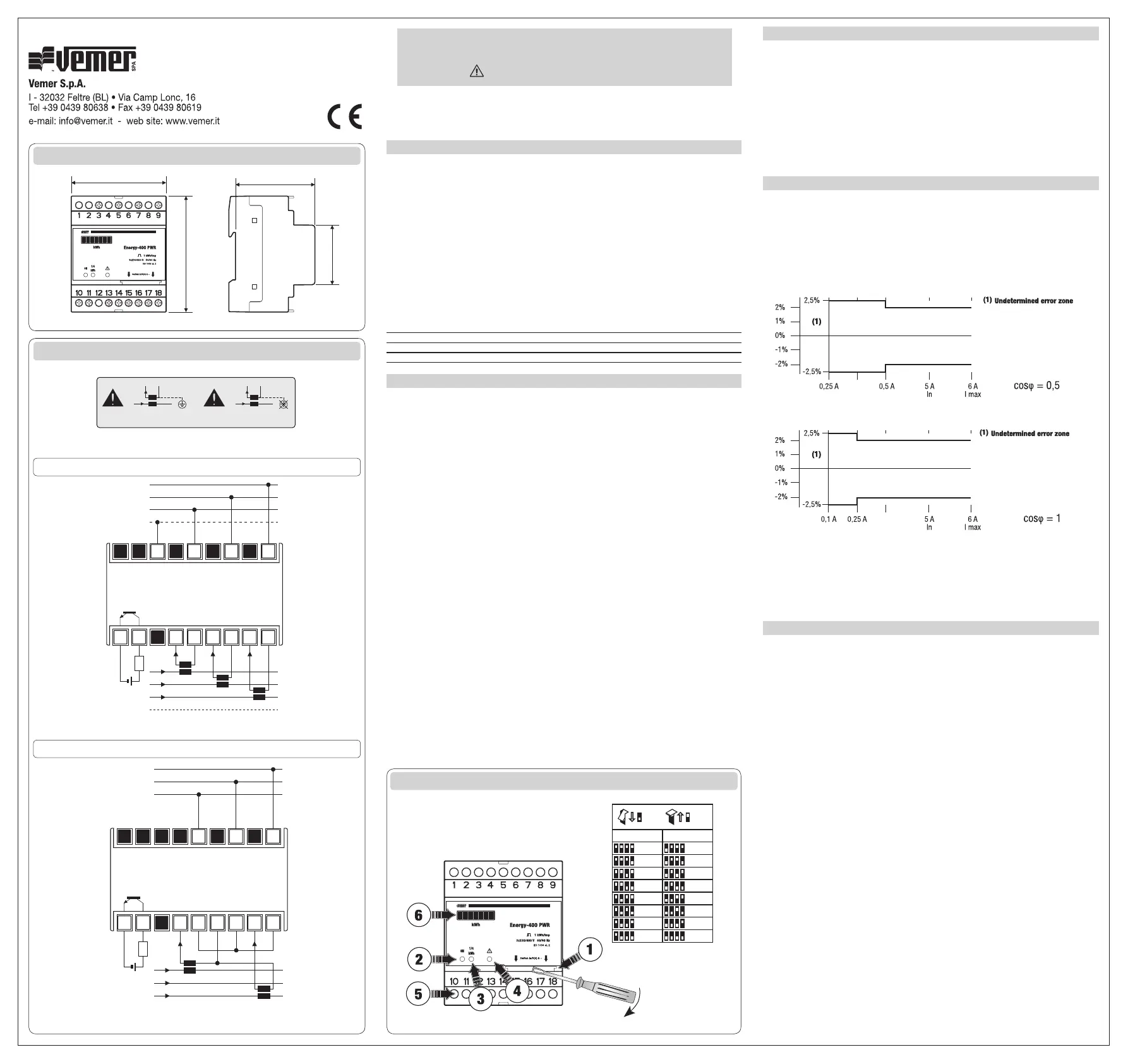
INSTRUMENT DESCRIPTION
➀Dip-switchforCTsetting
➁Green warning light:lightsuptoindicatepoweron
➂Red warning light:flashestoindicatethattheinstrumentismeteringenergy
(1flash=¼kWh)
➃Yellow warning light:whenlittheinstrumentdetects¼kWhnegative(probable
incorrectentry)andremainslituntil¼kWhpositiveisdetected
ChecktheinsertionofCT:connectL1,L2,L3frompowerpaneltoP1ofCTand
connectP2ofCTtotheload.
➄Impulseoutput:Opticallyinsulated
➅Electro-mechanicalimpulsecounter:resolution1kWh
GUIDE TO INSTALLATION
1)Beforeinstallingtheinstrument,selecttherequiredtransformationratio,asshownin
panel C)
2)ForEnergy-3x130PWRimodelonly,theCTsecondariesmaybeconnectedtoearth
3)TheinstrumentshouldbeconnectedasshowninthepanelB),inaccordancewiththe
CTcurrentdirections
4)Iftheerroristofallwithintheclasslimitsoftheinstrument,itisnecessarytousethe
current transformer in its linear operating field.
5)IftheinstrumentisactivethepowershouldbeswitchedofftochangetheCTratio.
6)Incaseofchangestothedip-switchwiththeinstrumentactived,theselocksinfault
conditionwithredandgreenlightsalwayson.Inthisconditiontheinstrumentdoesn’t
coun.
Torestorethecorrectoperation,repositiontheDIPswitchesintheinitialconditionor
resettheinstrumentbyremovingandrestoringpower.
REFERENCE STANDARDS
ConformitytoEUdirective:
2004/22/EC (MID)
2006/95/EC (Low Voltage - LVD)
isdeclaredwithreferencetothefollowingharmonisedstandards:
EN 61010-1
EN50470-1andEN50470-3
V3IS00244-100_02-2013
Mod.ENERGY-400 PWR
Mod.ENERGY-3x130 PWR
ENERGY-3x130 PWRi
Dimensions (A)
Connection diagrams (B)
Instrument description (C)
+
1
2
3
4
5
6
10
11
12
13
14
15
7
8
9
16
17
18
L3
L1
L2
L3
L2
L1
2 CT connection (PWRi only) WITHOUT neutral (3 wires)
1 kWh/pulse
Pulse output
I ≤ 20 mA
9÷24 VCC
PWRi
P1P2
S1S2
I
PWR
P1P2
S1S2
I
5
10
25
50
200
250
300
400
x/5 A
12
3
4
x/5 A
12
3
4
75
100
125
150
500
600
800
1000
ONOFF
N
L3
N
L1
L2
5
6
7
8
9
14
15
16
17
18
1
2
3
4
10
11
12
13
+
L3
L2
L1
3 CT connection WITH or WITHOUT neutral (3 or 4 wires)
1 kWh/pulse
Pulse output
I ≤ 20 mA
9÷24 VCC
72
60
87
45
1
4
6000
1
4
6000
Produktspecifikationer
| Varumärke: | Vemer |
| Kategori: | Mätutrustning |
| Modell: | Energy-3x130 PWRi |
Behöver du hjälp?
Om du behöver hjälp med Vemer Energy-3x130 PWRi ställ en fråga nedan och andra användare kommer att svara dig
Mätutrustning Vemer Manualer

2 Oktober 2024
22 September 2024
26 Augusti 2024
17 Augusti 2024
15 Augusti 2024
15 Augusti 2024
10 Augusti 2024
9 Augusti 2024
7 Augusti 2024
3 Augusti 2024
Mätutrustning Manualer
Nyaste Mätutrustning Manualer
3 April 2025
3 April 2025
3 April 2025
3 April 2025
3 April 2025
3 April 2025
3 April 2025
3 April 2025
3 April 2025
3 April 2025