Dormakaba EM 504 Bruksanvisning
Dormakaba ej kategoriserat EM 504
Läs gratis den bruksanvisning för Dormakaba EM 504 (3 sidor) i kategorin ej kategoriserat. Guiden har ansetts hjälpsam av 22 personer och har ett genomsnittsbetyg på 4.3 stjärnor baserat på 2 recensioner. Har du en fråga om Dormakaba EM 504 eller vill du ställa frågor till andra användare av produkten? Ställ en fråga
Sida 1/3
P/N 3101015 ISSUE 2 © 2006
Installation Instructions for EM EXT Series
Door Holder Extension Kits
Description
The Dorma ACC, ER Series Door Holder Extension Kits are
used where it is desired to hold doors open and where a standoff
distance between the magnet assembly and the armature base
is required. The extension rod kit can be used with Dorma EM
Series Door Holders. Parts from these door holders are used
with the extension kits to form a complete unit.
Model NumberExtension Range
ACC,ER 1.5 PKG1 1/2" (38 mm) Fixed
ACC, ER 2.5 PKG2" (51 mm) Fixed
ACC, ER 7 PKG 5-3/8 - 6-3/8" (137 - 162 mm)
ACC, ER 12 PKG 7-3/8 - 10-3/8" (187 - 264 mm)
Specifications
shown in Figure 2 or Figure 3 as applicable. If
bushings are damaged, replace with bushings supplied
with the door holder extension kit.
c.Insert the extension rod into the armature base and
secure with #10-32 x 1 1/2" (38 mm) armature securing
screw (Figures 1 - 3).
d.Insert spherical bushings (supplied) and flat washers
(supplied with EM EXT 7" and EM EXT 12" only) into
the extension rod assembly as shown in Figure 2 or
Figure 3, as applicable. Secure catch plate in
extension rod using #10-32UNF x 1" (25 mm) securing
screw (Figure 2).
e.For adjustable units only, adjust the extension length
by loosening the knurled locking nut, extending the
rod to the desired length and retightening the knurled
locking nut (Figure 2).
NOTE:Proper alignment of the catch plate and the
electromagnet helps ensure sufficient holding force.
f.Align the catch plate with the electromagnet by
moving the extension arm up or down and back or
forth while simultaenously adjusting the catch plate
against the magnet. There should be no gap between
the catch plate and the magnet.
g.After the desired extension length and contact
alignment have been achieved, perform the following
(Figure 2):
1.Using a 5/32" (4 mm) Allen Wrench (supplied),
lock the extension arm into position by tightening
the armature securing screw (Figure 2). Do not
overtighten.
h.Perform an operational check of the Electromagnetic
Door Holder as outlined in the installation instruction
provided with the door holder.
2.For more detailed information on installation of the door
holders, see the instructions supplied with the door holder.
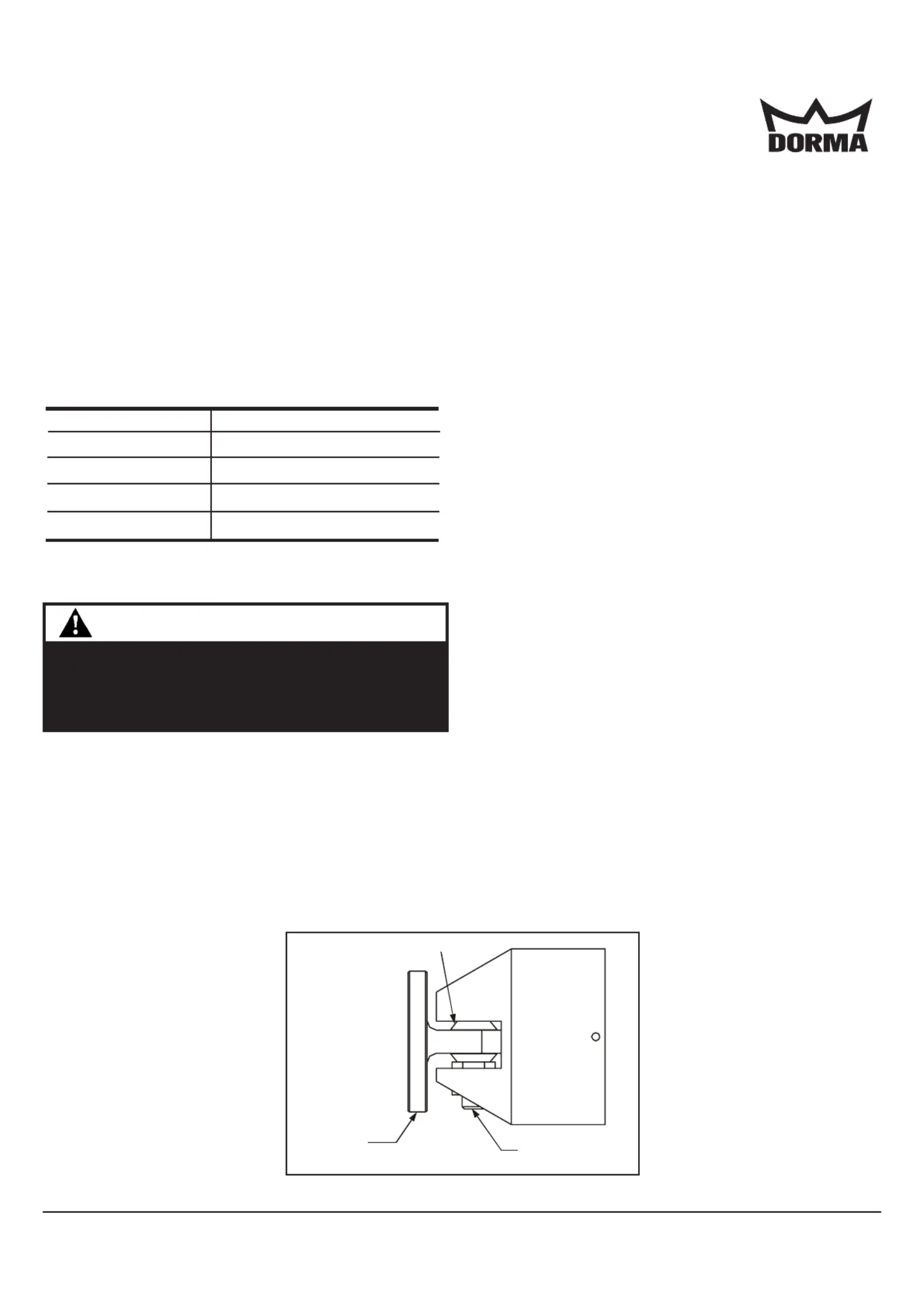
Figure 1. Armature Base Assembly
WARNING
The extension kits project a significant distance from
the doors they are mounted on and should, therefore,
be mounted as high as possible to preclude interfer-
ence or personal injury.
Installation
1.Install the extension kit as follows.
a.Remove the #10-32 x 1 1/2" (38 mm) armature
securing screw and remove the catch plate from the
armature base (Figure 1).
b.Insert spherical bushings (removed in Step 1.a) as
DORMAArchitectural hardware * Dorma Drive - Drawer AC, Reamstown, PA 17567 www.dorma-usa.com
Catch Plate
(2) Spherical Bushings
#10-32 x 1 1/2" (38 mm)
Armature Securing Screw
Note: Extension ranges published are with no catch
plate attached.
Produktspecifikationer
| Varumärke: | Dormakaba |
| Kategori: | ej kategoriserat |
| Modell: | EM 504 |
Behöver du hjälp?
Om du behöver hjälp med Dormakaba EM 504 ställ en fråga nedan och andra användare kommer att svara dig
ej kategoriserat Dormakaba Manualer

13 Augusti 2025
11 Augusti 2025
10 Augusti 2025
10 Augusti 2025
10 Augusti 2025
10 Augusti 2025
10 Augusti 2025
10 Augusti 2025
10 Augusti 2025
10 Augusti 2025
ej kategoriserat Manualer
Nyaste ej kategoriserat Manualer
3 April 2026
3 April 2026
3 April 2026
3 April 2026
3 April 2026
3 April 2026
3 April 2026
3 April 2026
3 April 2026