Fantini Cosmi L02A Bruksanvisning
Fantini Cosmi Termostat L02A
Läs gratis den bruksanvisning för Fantini Cosmi L02A (1 sidor) i kategorin Termostat. Guiden har ansetts hjälpsam av 32 personer och har ett genomsnittsbetyg på 4.2 stjärnor baserat på 2 recensioner. Har du en fråga om Fantini Cosmi L02A eller vill du ställa frågor till andra användare av produkten? Ställ en fråga
Sida 1/1
To get access to the parameter configuration menu, press button ■ + for 5 seconds.
With button ■
or select the parameter to be modified.
Press button ■
to display the value.
By keeping button ■
pressed, use button to set the desired value. or
When button ■
is released, the newly programmed value is stored and the following parameter is displayed.
To exit from the setup, press button ■
or wait for 30 seconds.
PARRANGEDESCRIPTION
SCL
1°C;
2°C;
°F
Readout scale (see table of input specifications)
Caution: upon changing the value, it is then absolutely necessary to the param-SCLreconfigure
eters relevant to the absolute and relative temperatures (, , , etc..)SPLSPH1SP1HY
SPL
-50°...SPHMinimum limit for setting1SP
SPH
SPL...150°Maximum limit for setting.1SP
1SP
SPL... SPHSetpoint (value to be maintained in the room).
1CM
HY; PIDControl mode.
With =H you select control with hysteresis: parameters , are used.1CMY1HY1T01T1 and
With =PID you select a Proportional-Integral-Derivative control mode: parameters , , 1CM1PB1IT
1DT1AR1CT, , will be used
1CH
REF; HEARefrigerating (REF) or Heating (HEA) control mode.
1CM=HY
1HY
0...19.9°OFF/ON thermostat diferential. With =0 the output is always of 1HYff.
1T0
0...30minMinimum of time.f
Afteroutputbeenturnedf,itremainsinactiveminutes 1 has of for 1T0regardless of the
temperature value measured.
1T1
0...30minMinimum on time. ().the following parameter will be 1PF
Afteroutput1 has beenturnedon, itremainsactive for 1T1minutes regardless of the temperature
value measured.
1CM=PID
1PB
0...19.9°Proportional bandwidth.
Temperaturetakesbychangingcontrol place the
ON of the the closer the timeoutput:temperature
to the the less of setpoint,timeactivation.Asmall
proportionalbandincreases the promptness of
response of the to systemtemperaturevariations,
butmakeitstable.Atends to less purely
proportionalstabilisestemperature control the
withinproportionalbandbutthe does not cancel
the deviation from setpoint.
With =0 the output is always o1PBff.
1IT
0...999sIntegral action time.
The error cancelled an steady-stateisbyinserting
integralaction.integralactiontime,determines The
the speed the withwhichsteady-statetemperature
isachieved,buthigh(low)maybe a speed 1IT the
causeovershootinstabilityinof and the response.
With =0 the integral control is disabled.1IT
1DT
0...999sDerivative action time.
Response overshootmaybereduced
byinserting
a derivativeAction.A highderivativeaction(1DT
high)makessystemverysensitive the to small
temperaturevariationcausesinstabilitys and . With
1DT=0 the derivative control is disabled.
1AR
0...100%Reset of integral action time referred to 1PB
Decreasingreducesintegralactionzone,consequentlythe parameter 1ARthe control and the
overshoot (see figure on paragraph ).1IT
1CT
1...255sCycle time.
It’s the the ON changes. The the to controlled periodinwhichoutputtimequickersystembe
reacts to the smaller the order to temperaturevariations,cycletimemustbe,inobtainhigher
temperature stability and less sensitivity to load variations.
1PF
ON/OFFOutput state in case of probe failure.
OAU
NON;
THR;
AL0;
AL1
AUX output operation.
NON : output disabled (always of). (fthe next parameter will be ATM)
THR: output programmed for second thermostat control ().the next parameter will be 2SM
AL0: contacts open when an alarm condition occurs (the next parameter will be ATM).
AL1: contacts make when an alarm condition occurs (the next parameter will be ATM).
OAU=THR
2SM
ABS;
REL
Setpoint 2 mode.
Channel 2 setnt ma e asolpoiybbu(te 2SM=ABS), or a dfferentiial relate to setivpoi(nt 1 2SM=REL)
2SM=ABS
2SP
SPL...SPHAuxiliary output switchover temperature ()the next parameter will be 2CH
2SM=REL
2DF
-19.9...19.9°Temperature diferential relative to The auxiliary output setpoint is equal to f1SP. 1SP2DF+
ON/OFF refrigerating control
(=H1CMY, =REF)1CH
ON/OFF heating control
(=H1CMY, =HEA)1CH
1SP
1SP+1HY
T[°]
ON
OFF
1SP1SP-1HY
T[°]
ON
OFF
Time
Terutarepme
Process
temperature
Overshoot
Steady-stateerror
1PB
1SP
Time
Terutarepme
Process
temperature
Overshoot
1PB
1PBx1AR%
integralcontrol
actionarea
1SP
Time
Terutarepme
Process
temperature
Overshoot
1PB
1SP
2SP
2SP+2HY
T[°]
ON
OFF
2SP2SP-2HY
T[°]
ON
OFF
ON/OFF control in refrigeration
(=ABS, =REF)2SM2CH
ON/OFF control in heating
(=ABS, =HEA)2SM2CH
1SP+2DF
1SP
2DF>0
1SP+2DF+2HY
T[°]
ON
OFF
1SP
1SP+2DF
2DF<0
1SP+2DF-2HY
T[°]
ON
OFF
ON/OFF control in refrigeration. Setpoint 2
relative to setpoint 1 (=THR, =REF)OAU2CH
ON/OFF control in heating. Setpoint 2
relative to setpoint 1 (=THR, =HEA)OAU2CH
Power supply
12Vac/dc ±10%, 2W (L02AI-/L02CI-/L02DI-)
110 - 230ac±10%, 50/60Hz, 3W (L02AM-/L02CM-/L02DM-)V
Relay outputs
Inputs
see table of input specifications
Measurement range
see table of input specifications
Measurement accuracy
see table of input specifications
Operating conditions
-10 … +50°C; 15%...80% U.R.
CE (Reference Norms)
EN60730-1; EN60730-2-9;
EN55022 (Class B); EN50082-1
Front protection
IP55
OAU=THR
2CH
REF; HEARefrigerating control (REF) or heating control mode (HEA) for the auxiliary output.
2HY
0...19.9°Diferential of thermostat 2. With =0 the auxiliary output always remains of2HYff.
2T0
0...30minMinimum of time.f
Afteroutput2 has beenturnedof f,itremainsinactivefor 2T0minutesregardless of the temperature
value measured.
2T1
0...30minMinimum on time.
Afteroutput 2 has beenturned on,itremains active for 2T1 regardless of the minutestemperature
value measured.
2PF
ON/OFFAuxiliary output state in case of probe failure.
ATM
NON;
ABS;
REL
Alarm threshold management.
NON all temperat:ure alarms are inhibi(ted the following parameter will be SB).
ABS: the values programmed n iALA and represent the real alarm thresholds.AHA
REL: the values programmed in ALRand AHRare alarm differentials referred to 1SPand 1SP+1HY.
ATM=ABS
ALA
-50°...AHALow temperature alarm threshold.
AHA
ALA...150°High temperature alarm threshold.
ATM=REL
ALR
-12.0...0°Low temperature alarm diferential. f
With =0 the low temperature alarm is excludedALR
AHR
0...12.0°High temperature alarm diferential. f
With =0 the high temperature alarm is excludedAHR
ATD
0...120minDelay before alarm temperature warning.
SB
NO/YESStand-by button enabling.
INP
0mA/4mA,
T1/T2
ST1/SN4
Sensor input selection (see table of input specifications).
WARNING: “0mA/4mA”, and “T2” are not available
In the models L02A--/L02D-- only.
RLO
-19.9...RHIMinimum range value (function not available)
RLO takes the minimum value measured by the transmitter (i.e. the value matching 0V, 0/4mA).
RHI
RLO...99.9Maximum range value (function not available)
RHI takes the maximum value measured by the transmitter (i.e. the value matching 1V, 20mA)
OS1
-12.5...12.5° T1 offset.Probe
TLD
1...30minDelay for minimum temperature (TLO) and maximum temperature (THI) logging.
SIM
0...100Display slowdown
ADR
1...255address for PC communication (function not available)
1SP
1SP-ALR
T[°]
ON
OFF
1SP+1HY+AHR
1SP1SP-1HY-ALR
1SP+AHR
T[°]
ON
OFF
Temperature alarm with relative thresholds,
refrigerating control (ATM1CH=REL, =REF)
Temperature alarm with relative thresholds,
heating control (ATM1CH=REL, =HEA).
DISPLAY
During normal operation, the display shows either the temperature measured or one of the following indications:
OFF
Controller in stand-by
TUN/xx.x
Controller in autotuning
OR
ProbeT1 overrange or failure
E1
In tuning: timeout1 error
HI
Room high temperature alarm
E2
In tuning: timeout2 error
LO
Room low temperature alarm
E3
In tuning: overrange error
MENU INFO
The information available in this menu is:
THI
Maximum temperature recorded
LOC
Keypad state lock
TLO
Minimum temperature recorded
Access to menu and information displayed.
Press and immediately release button ■
.
With button ■
or select the data to be displayed.
Press button ■
to display value.
To exit from the menu, press button ■
or wait for 10 seconds.
Reset of THI, TLO recordings
With button ■
or select the data to be reset.
Display the value with button ■
.
While keeping button ■
pressed, use button .
CHANNEL 1 SETPOINT (display and modification of desired temperature value)
Press and release button ■
: the ED LLbli1 nks, the dspla shoiyws 1P for 1 second and then the setnt assocSpoiiated value.
Press buttons ■
or to set the desirevalud e (adjustment s iwithin the minimum SPL and maximum SPHlimit.)
To store the new value press button ■
, or wait for 10 seconds.
To go back to normal mode without saving the new value, press ■
.
CHANNEL 2 SETPOINT
Withauxiliaryoutput(the set as thermostat control ■=THR),itOAU’s to 2 the normal possiblemodifysetpointduringoperation
of the controller.
Press and release button ■
:LEDL2blinks,displayshows2Sifsetpointisabsolutethe the P for 1 second 2 an threshold
(=ABS),alternativelydisplayshows2SM the 2DF,ifsetpointisrelativesetpoint(=REL),value 2 a threshold to 1 2SM then the
associated to the parameter appears.
Press buttons ■
or to set the desired value.
To store the new value press button ■
or wait for 10 seconds.
To go back to normal mode without saving the new value, press ■
.
STAND-BY
Button ,when pressed for 3 seconds, allows the controller to e pbut on a standbyor output control to be resumed (with SB=YES only).
KEYPAD LOCK
The attempted the controllers keypadlockavoidsundesired,potentiallydangerousoperations,whichmightbewhenisoperating
inpublicmenu,=YESinhibitfunctionsbuttons. a place. In the INFO set parameter LOC to all of the To normal resumeoperation
of keypad, adjust setting so that LOC=NO.
CONTROLLER AUTOTUNING IN PID MODE
Before starting
In the mode set =PID; that matches the mode setup(seeconfigurationparameters):1CMmakesure1CHdesiredoperation
(=REF for refrigerating control, =HEA for heating control); then adjust setpoint at the desired value.1CH1CH1SP
Start autotuning
Duringoperation,keepbuttons normal
+ pressed for seconds. 1CT on the 3blinksdisplay. + or set the With cycle
timeindefinedynamicbe order to the of the process to controlled. To the press abortautotuningfunction,
; to start autotuning
press
+ or wait for 30 seconds.
During autotuning
Duringentireautotuningphase,displayTUNwithactualtemperaturemeasured.powerfailure, the the alternates the In case of
whenpowerisresumed,initialautotestphase,resumesautotuningfunction. after the the controller the To the abortautotuning,
withoutmodifyingpreviousparameters,keepbutton the control
pressed for seconds. the has place 3Afterautotuningtaken
successfully, the controller updates the control parameters and start to control.
Errors
If the autotuning function failed, the display shows an error code:
E1 the controller not the the Increase timeout1error:couldbringtemperaturewithinproportionalband.■inheating 1SP case of
control, vice versa, decrease in case of refrigerating control and re-start the process.1SP
E2 the has not ended the Re-start the timeout2error:autotuningwithinmaximumtimeallowed(1000cycletimes).autotuning ■
process and set a longer cycle time 1CT.
E3temperatureoverrange:checkwascausedbyprobemalfunction, that the error not a then decrease ■inheating 1SP case of
control, vice versa increase in case of refrigerating control and then re-start the proce1SPss.
To eliminate the error indication and return to the normal mode, press button ■
.
Control improvement
To reduce overshoot, reduce the integral action reset ■1AR
To increase the response speed of the system,reduce the proportionabanl d ■1PB. Catuion:doing this makes the system less stable.
To reduceswingsinsteady-statetemperature,increase the integralactiontime ■systemstability1IT; isthusincreased,although
its response speed is decreased.
To the speed of response to the the increasevariationsintemperature,increasederivativeactiontime ■Caution:high 1DT. a
value makes the system sensitive to small variations and it may be a source of instability.
RECALIBRATION
Have a precision reference thermometer or a calibrator to hand. Ensure that ■=0 and =0.OS1SIM
Switch the controller of then on again.f ■
During the auto-test phase, press buttons ■
0AD+ and keep them pressed till the controller shows .
Withbuttons ■
and select or a of a constant the scale 0ADSAD0AD: allowscalibration0,insertingcorrectionoverwhole
of a of the top part of the scale a the measurement. SADallowscalibrationmeasurementwithproportionalcorrectionbetween
calibration point and 0.
Press ■
to the and then + or to the read the the displayvalueusemakevaluecoincidewithvaluemeasuredby
reference instrument.
Exit from calibration by pressing button ■
.
Insert the controller through a hole measuring 71x29 mm;■
Makesureelectricalconnectionscomplywith“wiringdiagrams”. that the paragraph To the effects of reduceelectromagnetic ■
disturbance, keep the sensor and signal cables well separate from the power wires.
Fix the controller to the panel means of the bysuitableclips,bypressinglygently; iffitted,check that the adheres rubbergasket■
to the panel perfectly, in order to prevent debris and moisture infiltration to the back of the instrument.
Place the probeT1 inside the room in a point that truly represents the temperature of the stored product. ■
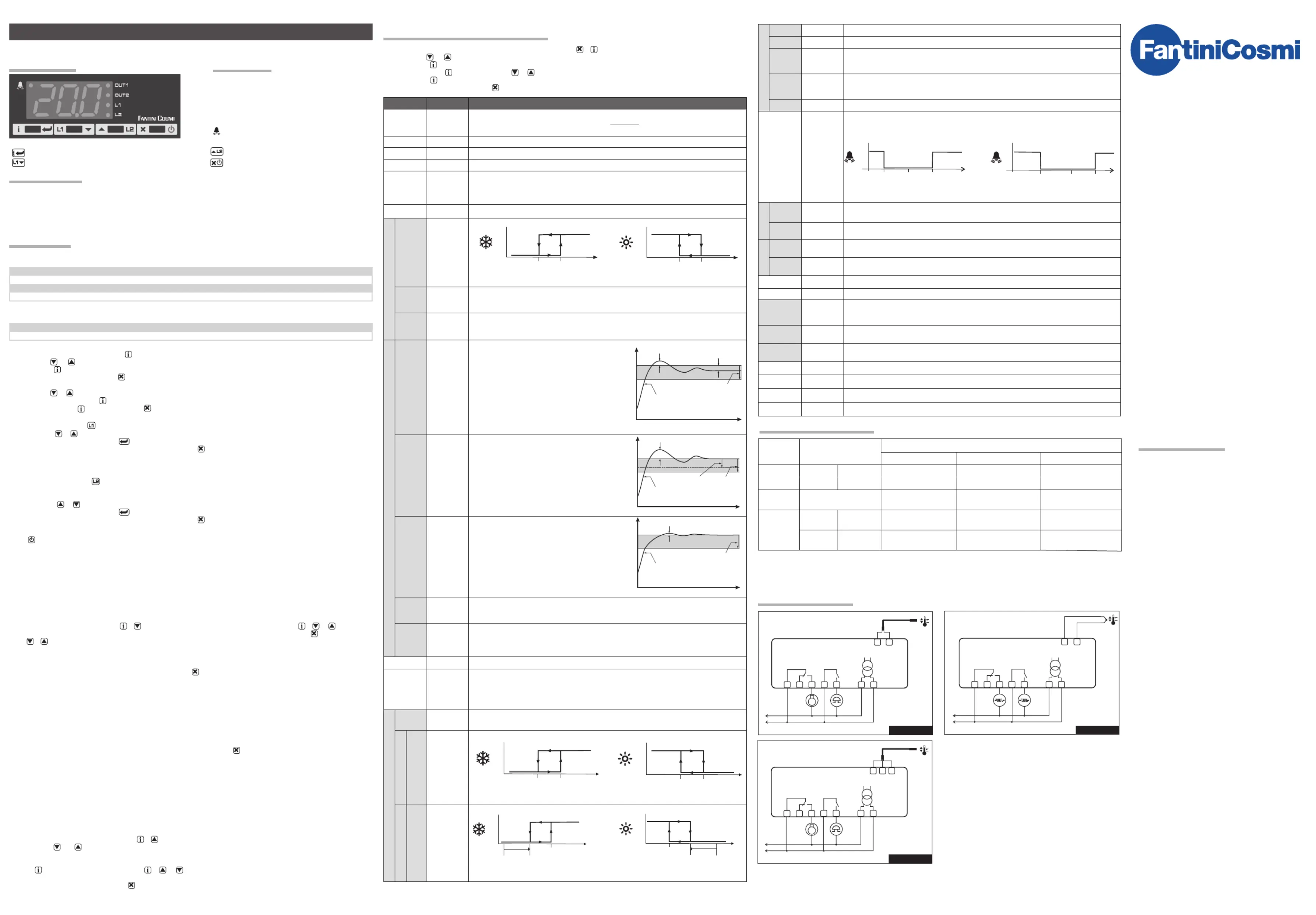
OUT1
OUT2
L1
L2
Channel 1 output
Channel 2 output
Alarm
Channel 1 setpoint modification
Channel 2 setpoint modification
Info / Enter button
Fig.1 - Front panel
Modify Setpoint 1 / Decrease button
Increase / Modify Setpoint 2 button
Exit / Stand-by button.
Thank you for having chosen a Fantini Cosmi product. Before installing the instrument, please read these instructions carefully
to ensure maximum performance and safety.
INSTRUCTION FOR USE
L02DM- / L02DI-
115...~ (L02DM-) o 12Vac/dc (L02DI-)230V
OUT2OUT1
+
-
10
11
1234
5
67
L02CM- / L02CI-
115...~ (L02CM-) o 12Vac/dc (L02CI-)230V
OUT2
WRW
9
10
11
4
5
67
L02AM2 / L02AI2B
115...~ (L02AM2) o 12Vac/dc (L02AI2B)230V
OUT2OUT1
10
11
1234
5
67
OUT1
123
MODELINPUT
RANGE [MEASUREMENT ACCURACY]
SCL=1°CSCL=2°CSCL=°F
L02D--
INP=T1---TC “J”0÷450°C [ < ±3°C ]
32÷842°F [ < ±5°F ]
L02C--PT100
-50/-19.9÷99.9/150°C
[ < ±0.3°C ]
0÷400°C
[ <±1°C(0÷400°), ±2°C ]
32÷752°F
[ <±2°F(32÷752°), ±4°F]
L02A--
INP=ST1
PTC 1000 Ω
(LS120)
-40/-19.9 ÷ 99.9/105°C
[<±0.3°C(-40÷130°),±1°C]
-40 ÷ 105°C
[<±0.3°C(-40÷130°),±1°C]
-40 ÷ 221°F
[<±0.6°F(-40÷221°),±2°F]
INP=SN4
NTC 10K Ω
(LS130)
-40/-19.9 ÷ 99.9/105°C
[<±0.3°C(-40÷100°), ±1°C]
-40 ÷ 105°C
[<±0.3°C(-40÷100°),±1°C]
-40 ÷ 221°F
[<±0.6°F(-40÷210°),±2°F]
OUT1
10A 24Vac/dc
(L02AI2B/L02CI2B/L02DI2B)
OUT2
1A 24Vac/dc
OUT1
12(4)A 240Vac
(L02AM2/L02CI1B/L02CM-/L02DI1B/L02DM-)
OUT2
7(2)A 240Vac
DESCRIPTION
INDICATIONS
CONFIGURATION PARAMETERS
INPUT SPECIFICATIONS
TECHNICAL DATA
WIRING DIAGRAMS
INSTALLATION
OPERATION
GB79193B
FANTINI COSMI S.p.A.
Via dell’Osio, 6
20090 Caleppio di Settala, Milano, ITALY
Ph. +39 02 956821 | Fax +39 02 95307006
L02...
Produktspecifikationer
| Varumärke: | Fantini Cosmi |
| Kategori: | Termostat |
| Modell: | L02A |
Behöver du hjälp?
Om du behöver hjälp med Fantini Cosmi L02A ställ en fråga nedan och andra användare kommer att svara dig
Termostat Fantini Cosmi Manualer

13 Oktober 2025
12 Oktober 2025
12 Oktober 2025
18 Augusti 2025
19 Juli 2025
18 Juli 2025
1 April 2025
1 April 2025
1 April 2025
Termostat Manualer
Nyaste Termostat Manualer
2 April 2026
1 April 2026
31 Mars 2026
30 Mars 2026
19 Mars 2026
16 Mars 2026
14 Mars 2026
25 Februari 2026
5 Oktober 2025
2 Oktober 2025