Salus CB500CO Bruksanvisning
Salus ej kategoriserat CB500CO
Läs gratis den bruksanvisning för Salus CB500CO (2 sidor) i kategorin ej kategoriserat. Guiden har ansetts hjälpsam av 42 personer och har ett genomsnittsbetyg på 4.1 stjärnor baserat på 7 recensioner. Har du en fråga om Salus CB500CO eller vill du ställa frågor till andra användare av produkten? Ställ en fråga
Sida 1/2
INTRODUCTION
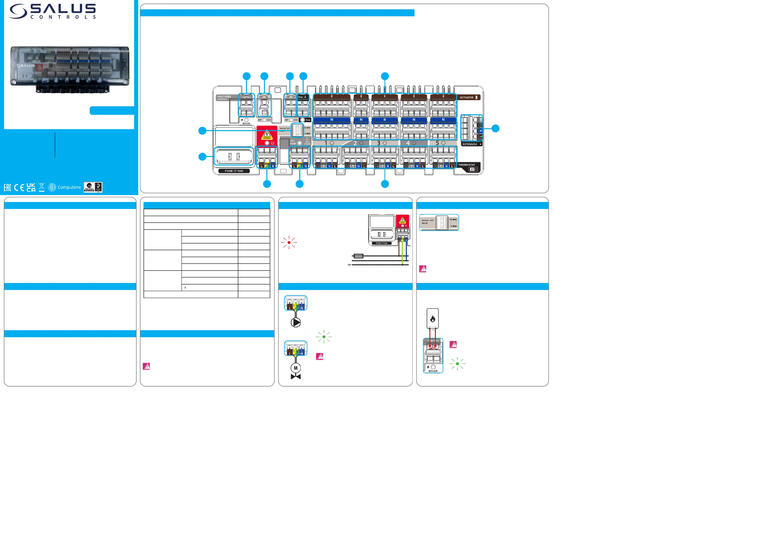
CONTROL BOX DESCRIPTION
1. FUSE
2. POWER SUPPLY
3. PUMP/VALVE CONTROL OUTPUT
4. BOILER DELAY - JUMPER SETTINGS
5. BOILER CONTROL OUTPUTPRODUCT COMPLIANCE
SAFETY INFORMATION
1. Cartridge fuse - 5 x 20 mm T10A (replaceable)
2. Power supply - 230V
3. Pump/Valve supply - 230V
4. Boiler delay - jumper settings
5. Boiler control output - volt-free
6. Heating / Cooling - 230V input for Heat/Cool Changeover
7. Heating / Cooling - volt-free contact for Heat/Cool Changeover
8. Dew point sensor connection - volt-free
9. NC Actuators output connections - 230V
10. Thermostats connections
11. CB500X extension connection
The new CB500CO control box is the main element of the underoor heating/cooling control system.
It has a built-in module that controls the heat and cool sources. The control box allows you to control
5 dierent zones. The number of controlled zones can be increased up to 20 zones by using additional
CB500X extension modules (CB500CO main control box + three CB500X extension modules). Each
individual zone can be operated by one thermostat. The thermostat which requires a 230V power
supply has to be powered directly from the control box. The CB500CO has volt-free contacts designed
to control a boiler. The CO-Contact from the heat pump allows you to switch from Heating to Cooling.
The CO Contact can be volt-free or 0 respective 230V. It is equipped with 230V voltage outputs for a
pump and actuators. The spring clamps provide quick and convenient wiring connections. The control
box is designed to work with NC (normally closed) type actuators. It is recommended to mount it on
a surface or on a DIN rail.
Main fuse is located under the housing cover next to power supply terminals and secures the control
box and the devices connected to it. Use ceramic tube slow blow 250 V ROHS fuses (5x20 mm) with
nominal max current 10A. To replace fuse remove the fuse holder with a at screwdriver and pull out
the fuse.
Power supply for control box is 230 V ~ 50Hz.
Three wire installation should be made in
accordance with the current applicable regulations.
PUMP/VALVE output - this is a 230 V AC output that controls the pump and
valve of the heating and cooling systems. If any of thermostats connected
to the CB500CO send heating / cooling signal - PUMP/VALVE output will
be activated after 3 minutes. If all of the thermostats connected to the
CB500CO stop sending heating / cooling signal - PUMP/VALVE output will
be deactivated after 3 minutes.
This jumper sets the turn o delay time of the BOILER control
outputs.
Boiler output - this is a volt-free output (COM / NO) which controls heating
system boiler. If any of thermostats connected to the control box sends
signal for heating, BOILER output is activated after 3 minutes delay, giving
permission for boiler to turn ON. If all thermostats connected to the control
box stop sending signal for heating, then BOILER output is deactivated -
this is the signal for boiler to turn OFF (BOILER output can work with 0min
or 15min delay - please refer to chapter 4).
Boiler ON/OFF contacts
(according to the
boiler’s manual)
When the Pump/Valve control output is activated, the
LED shows a constant green light
When the BOILER output is activated, the LED shows a
constant green light.
WARNING!
Before starting the installation, disconnect the 230V power supply!
The LED will illuminatered
inidicating that the control box is
connected to the power supply.
NOTE: Replacement of the fuse to be carried out only when the control box is disconnected
from power supply (230 V ~).
NOTE: When the jumper is set to 15 minutes delay time you must ensure hydraulic ow in the
system when all actuators are closed. Use a bypass or dierential pressure valve.
This product complies with the essential requirements and other relevant provisions of the following
EU Directives: EMC 2014/30/EU, Low Voltage Directive LVD 2014/35/EU, RoHS directive 2015/863/
EU. The full text of the EU Declaration of Conformity is available at the following internet address:
www.saluslegal.com.
Use in accordance with current national and EU regulations. The product is intended for indoor use
only in dry conditions. The CB500CO should not be installed in areas where it may be exposed to
water or damp conditions. Installation must be carried out by a qualied person in accordance to
current national and EU regulations. Before attempting to setup and install, make sure that CB500CO
is not connected to any power source. Incorrect installation may cause damage to the control box.
2
1
4
310
11
56789
max
5(2) A
LN
LN
When the jumper is set to position (default setting) then the BOILER output (volt-free “0 MIN”
relays) are deactivated immediately when thermostats stop heating.
When the jumper is set to position then the BOILER outputs (volt-free relays) are“15 MIN”
deactivated 15 minutes after thermostats stop heating.
Quick Guide
SALUS Controls is a member of the Computime Group
Maintaining a policy of continuous product development SALUS Controls plc reserve the right to change specication,
design and materials of products listed in this brochure without prior notice.
SALUS Controls
Units 8-10, Northeld Business
Park, Forge Way, Parkgate
Rotherham, S60 1SD
T: +44 (0) 1226 323961
SALUS CONTROLS GMBH
Dieselstrasse 34
63165 Mühlheim am Main
Tel: +49 (0) 6108 825850
Email: [email protected]
V01
02/2024
www.saluscontrols.com
Control box (5 zones) 230 V
Model: CB500CO
230 V AC
L
N
TECHNICAL INFORMATION
Power Supply230 V AC 50 Hz
Total Load Max7 (2) A
Pump / Boiler / Heat Pump Relay Load Max5 (2) A
InputsHeat/Cool changeover230 V AC
Heat/Cool changeoverVolt-free
Dew point sensorVolt-free
OutputsBoiler controlVolt-free
Pump/Valve control230 V AC
Actuators230 V AC
Thermostat connections(L, N) Power Supply230 V AC
(CO) Output Heat/Cool changeover0 - 230 V AC
() Input Actuators 0 - 230 V AC
Dimensions [mm]270 x 110 x 55
WARNING!
DO NOT use 230V AC!
Produktspecifikationer
| Varumärke: | Salus |
| Kategori: | ej kategoriserat |
| Modell: | CB500CO |
Behöver du hjälp?
Om du behöver hjälp med Salus CB500CO ställ en fråga nedan och andra användare kommer att svara dig
ej kategoriserat Salus Manualer

28 September 2025
24 Augusti 2025
18 Augusti 2025
18 Augusti 2025
17 Augusti 2025
4 Augusti 2025
4 Augusti 2025
3 Augusti 2025
3 Augusti 2025
3 Augusti 2025
ej kategoriserat Manualer
Nyaste ej kategoriserat Manualer
3 April 2026
3 April 2026
3 April 2026
3 April 2026
3 April 2026
3 April 2026
3 April 2026
3 April 2026
3 April 2026