Salus KL08RF Bruksanvisning
Läs gratis den bruksanvisning för Salus KL08RF (2 sidor) i kategorin Smart hem. Guiden har ansetts hjälpsam av 31 personer och har ett genomsnittsbetyg på 4.5 stjärnor baserat på 8 recensioner. Har du en fråga om Salus KL08RF eller vill du ställa frågor till andra användare av produkten? Ställ en fråga
Sida 1/2
ZigBee network wireless wiring centre (8 zones),
230 V AC
Model: KL08RF
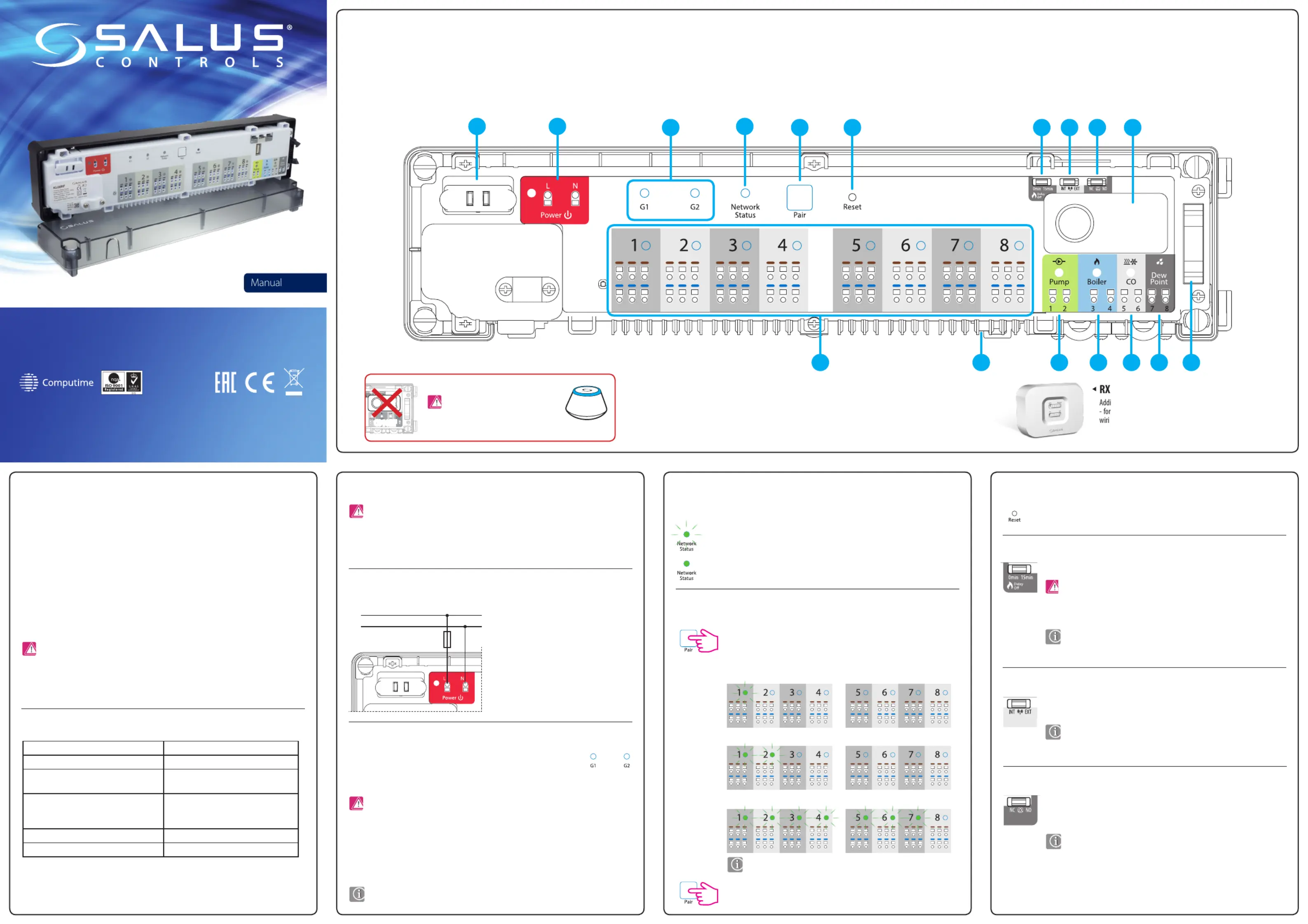
Introduction1. Fuse
Wiring centre description
2. Power Supply
3. Thermostat grouping status
4. Network Status diode
5. Pair button
6. Reset button
10RF (optional)
7. Delay jumper
8. INT/EXT antenna jumper
9. NC/NO actuators jumper
Technical Information
Product Compliance
Safety Information
This product complies with the essential requirements and other relevant provisions of Directives: EMC
2014/30/EU, LVD 2014/35/EU, RED 2014/53/EU and RoHS 2011/65/EU. The full text of the EU Declaration
of Conformity is available at the following internet address: www.saluslegal.com.
Use in accordance with the regulations. Indoor use only. Keep your device completely dry. Disconnect your device
before cleaning it with a dry cloth. This accessory must be tted by a competent person, and installation must
comply with the guidance, standards and regulations applicable to the city, country or state where the product
is installed. Failure to comply with the relevant standards could lead to prosecution.
This function is only available in Oine mode (together with CO10RF coordinator)
- it means MASTER thermostats will aect to SLAVE thermostats within specic group,
which is possible only when thermostats are paired with one KL08RF wiring centre
(optional + KL04RF) and have been assigned to gr. 1 or gr. 2.
How it works: If all thermostats of a given group will operate in automatic mode, then each of the thermostats
in a given group will work in the same way as the MASTER of this group. For example, if the MASTER thermostat
of Group 1 according to it’s programmed schedule maintains a comfort mode - all SLAVE type thermostats from
Group 1 will also maintain the comfort mode (the temperature is set individually for every thermostat). Similarly,
if the MASTER thermostat is set to Party or Holiday mode - SLAVE thermostats in his group will also work in
these modes.
The mains fuse is located under the housing cover, at the main terminals and protects the wiring centre and
devices powered by it. Use cartridge fuse-type 5 x 20 mm - nominal burn rate 12 A. To remove the fuse, lift
the socket with a at screwdriver and pull out the fuse.
- (LED is steady lit) - it means wiring centre is added to the ZigBee network and paired with CO10RF
or UGE600
- Checking the address of the wiring centre in the Zigbee network. To check the address of the
wiring centre in the ZigBee network (when using more than one) press the Pair button.
The wiring centre number is indicated by the number of LEDs at the zones:
LED diode statuses:
Functions of the Pair button:
- The wiring centre reset
(this function is described in detail on the second page of the manual).
- It is used to refresh the data, after moving jumpers 7,8 or 9.
The Reset button does not remove the wiring centre from the ZigBee network.
- (LED diode is blinking) - it means wiring centre is not connected to the network, but it is ready
for pairing with the coordinator (CO10RF) of the ZigBee network or the Internet gateway (UGE600)
Power supply for wiring centre is 230V ~, 50Hz.
Features of the installation:
• three-wire, with PE protective conductor,
• made in accordance with applicable regulations.
tional, wireless device control module that can be used
example - when we can’t use cable between the KL08RF
ng centre and the boiler.
Boiler o delay time.
There is an option to connect the 08RFA external antenna to the wiring centre.
If you use an additional antenna, place the jumper in the EXT position.
Select the type of the thermoelectric actuator connected to the wiring centre:
NC – actuator normally closed
NO – actuator normally opened
L
N
The KL08RF wireless wiring centre is a part of the iT600RF system. In combination with the wireless thermostats
from iT600RF series, KL08RF provides comfortable and reliable heating control. It is equipped with the control
outputs for the pump and boiler and has been designed to work with NC or NO actuators.
In Oine mode, communication with the wireless thermostats from iT600RF series must be done through
the CO10RF co-ordinating unit, which is in the package together with the wiring centre. To work in Online mode
(via the SALUS Smart Home app) KL08RF must be connected to the Internet gateway UGE600. In one ZigBee
network (Online or Oine) up to 9 KL08RF wiring centres can be connected. KL08RF increases ZigBee network
range.
12
57
11121713141516
891063
4
1. Cartridge fuse 5 x 20 mm 12 A
2. Power Supply
3. Thermostat grouping status
4. Network Status diode
5. Pair button
6. Reset button
7. Delay jumper
8. INT/EXT antenna jumper
9. NC/NO actuators jumper
10. ZigBee network coordinator
11. Terminals for actuators
12. Pump control output
13. Boiler control output
14. CO terminal
15. Dew point sensor input (humidistat)
16. Serial connector for the KL04RF extension
17. External antenna connector
15 sec
Jumper position change must be refreshed in the memory by pressing the Reset
button (short press).
Note: Within one group there may be only one MASTER thermostat (programmable) and the rest
must be SLAVE thermostats (non-programmable).
Note: Fuse replacement should be done when the wiring centre is disconnected from power supply
230 V AC.
Note: Pump (Pump output) and boiler (Boiler output) always starts 3 minutes after
receiving the heating signal from any thermostats paired with wiring centre. Pump
stops after 3 minutes, when the last thermostat stops sending demand for heat,
while the heat source (Boiler) will turn o after the time set with the jumper.
Jumper position change must be refreshed in the memory by pressing the Reset
button (short press).
Jumper position change must be refreshed in the memory by pressing the Reset
button (short press).
The grouping function is optional - thermostats do not have to be grouped, they can operate
independently.
Address 9 is indicated by lighting up 8 LEDs of all the zones and the Network
Status LED.
230 V AC
Adress 1
Adress 2
Adress 7
Power Supply230 V AC 50 Hz
Max load3 A
InputsCO terminal
Dew point sensor (humidistat)
OutputsPump control
Boiler control
Terminals for actuators
Radio frequencyZigBee 2,4 GHz
Dimensions [mm]355x83x67
Note: Don’t use CO10RF coordinator
with UGE600 simultaneously!
CO10RF
UGE600
I 2017
T: +44 (0) 1226 323961
Head Office:
SALUS Controls plc
SALUS House
Dodworth Business Park South,
Whinby Road, Dodworth,
Barnsley S75 3SP, UK.
www.salus-controls.com
SALUS Controls is a member of the Computime Group.
Maintaining a policy of continuous product development SALUS Controls plc reserve the right
to change specification, design and materials of products listed in this brochure without prior notice.
Produktspecifikationer
| Varumärke: | Salus |
| Kategori: | Smart hem |
| Modell: | KL08RF |
Behöver du hjälp?
Om du behöver hjälp med Salus KL08RF ställ en fråga nedan och andra användare kommer att svara dig
Smart hem Salus Manualer

28 September 2025
30 Juli 2025
29 Juli 2025
29 Juli 2025
28 Juli 2025
28 Juli 2025
28 Juli 2025
28 Juli 2025
26 Juli 2025
25 Juli 2025
Smart hem Manualer
Nyaste Smart hem Manualer
3 April 2026
2 April 2026
24 Mars 2026
22 Mars 2026
22 Mars 2026
22 Mars 2026
22 Mars 2026
21 Mars 2026
21 Mars 2026
20 Mars 2026