Salus RT10 Bruksanvisning
Läs gratis den bruksanvisning för Salus RT10 (2 sidor) i kategorin Termostat. Guiden har ansetts hjälpsam av 32 personer och har ett genomsnittsbetyg på 4.6 stjärnor baserat på 3 recensioner. Har du en fråga om Salus RT10 eller vill du ställa frågor till andra användare av produkten? Ställ en fråga
Sida 1/2
SALUS RT10
Electronic room thermostat for radiant panel,
radiator and convector heating systems
Installation and
operating instructions
General
Congratulations on choosing to purchase
a SALUS room thermostat. In selecting the
room temperature controller that can boast
some considerable advantages over its con-
ventional, mechanical counterparts. This
controller is very simple to use with its stan-
dard rotary knob and, with its state-of-theart
electronics, it can offer you unparalleled ease
of control for all manner of heating systems.
The RT10‘s features, which are described
in detail below, ensure that you can control
your heating system in a precise, easy and
energy-saving way.
Technical characteristics
Pulse width modulation (PWM)
Radiant panel heating systems tend to have a
problem with overshooting, i.e. rooms conti-
nue to be heated even after the desired tem-
perature has been reached and the valve has
been closed. The RT10 solves this problem
electronically and especially effectively using
what is known as pulse width modulation. By
continuously comparing set temperature with
actual temperature, the lengths of opening
times for the valve actuators are regulated
in such a way that the temperature is almost
completely prevented from exceeding or fal-
ling below the set temperature. In this way,
the required temperature setting is regulated
in a precise and convenient way.
Note: When the RT10 is used with radiator
or convector heating systems, pulse width
modulation can be switched off if necessary
(see ‚Basic settings‘ section).
Valve protection function
To ensure that valves remain movable and
ready for use even when they are unused for
considerable periods – e.g. over the summer
– the RT10 includes a valve protection func-
tion. Briefly once a week, even when there is
no requirement for any heat, the valve actua-
tors open the valves that they control.
Note: The valve protection function can be
switched off if it is not required (see ‚Basic
settings‘ section).
Temperature reduction
Timed and demand-oriented heating control
are amongst the best ways of managing hea-
ting energy in an economical way. The RT10
has an integrated temperature reduction
function which enables you to automatically
reduce the set temperature by 4K with no
need for any costly add-on installation on the
boiler controller. This ‚night reduction‘ can
be activated by an external signal, e.g. time
control from a terminal strip, or using a stan-
dard external timer.
Installation
The RT10 room thermostat is designed as
an electronic temperature controller for the
electrical fine adjustment of hot-water based
heating systems, and is used for controlling
electro-thermal valve actuators or other elec-
trical devices. It is vitally important that the
maximum switching current specified in the
technical specifications should not be excee-
ded! We are not liable for any form of impro-
per use.
This equipment must only be installed by
anauthorised, qualified engineer, and only in
accordance with the wiring diagram. Instal-
lation must also be in accordance with the
latest VDE regulations as well as your electri-
city supplier‘s regulations. The system must
be in a de-energised state whilst installation
is carried out, and all safety instructions
must be followed to the letter.
The control may only be mounted on a non-
conductive surface. Find a position for the
thermostat where it is not covered by curta-
ins, furniture or anything else. The controller
must not be installed too close to any heat
source (lights, stove, direct sunlight etc.),
nor should it be installed in a position where
it will be exposed to draughts. The control-
ler must be installed in a suitable location in
order for room temperature to be monitored
accurately and accordingly regulated with
precision.
Important:The thermostat must be dis-
connected from its power supply before its
housing is opened.
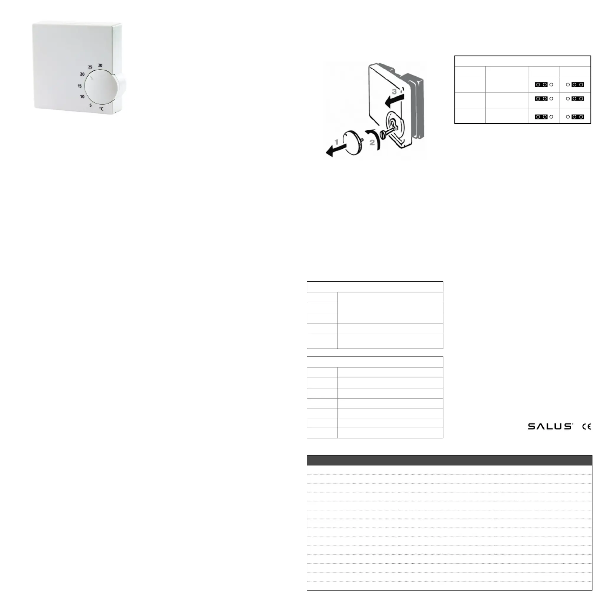
Wall mounting
The housing cover must be separated from
the base plate before the controller is fitted.
Follow the steps listed below:
Carefully pull off the adjuster wheel.1.
Remove the screw from under the adju-2.
ster wheel.
Open the housing by pulling off its cover 3.
on the adjuster wheel (right) side.
Now, using the screws supplied, screw the
base plate firmly to the wall or the flush-
mounted socket.
Connection
The thermostat must be wired in accordance
with the wiring diagram below:
RT10 230 V Model
Terminal
Lead for temperature reduction
NNeutral conductor supply lead
L230VAC power supply
Switch output (valve actuator, terminal
strip)
RT10 24 V Model
Terminal
Lead for temperature reduction
L2Neutral
NCCircuit closed once temperature reached
1
Common
NOCircuit open once temperature reached
2
L124VAC power supply
1
e.g. cooling unit
2
e.g. heating unit
Basic settings
The jumpers on the PCB can be used to turn
on or off various functions of the RT10:
RT10 Jumpers
Switch
FunctionONOFF
VP
Valve protection
function
PWM
Pulse width
modulation
Temperature
reduction
The factory setting for all these functions is
ON. You can change these settings according
to your own requirements by moving the
contact terminals on the jumpers.
Important: The contact terminals should not
be removed.
As long as the installation is carried out to a
professional standard, the criteria for protec-
tion class II will be satisfied.
Operation
The RT10 electronic room thermostat is
used for regulating the temperature in dry,
enclosed rooms with a normal environment
and maximum humidity of 95% (nonconden-
sing).
It is extremely simple and convenient to set
the desired room temperature using the
rotary knob. This electronic control system
ensures that the set room temperature is
maintained virtually without fluctuation and,
when required, automatically activates a red-
uction in temperature.
Never use anything other than a soft, dry
cloth to clean the unit. Never use any clea-
ning agents containing solvents or any sharp
objects to clean the unit!
Technical data230 V24 V
Product no.:412.100412.101
Operating voltage:230VAC / 50Hz24VAC / 50 Hz
Electronic switch output
Max. switching current:10 (2) A
Rated impulse voltage:4000 V
Max. no. of valve actuators:5 units - 3 W
Temperature range:5°C - 30°C
Degree of protection through casing:IP 30
Automatic function:type 1.C (EN 60730-1)
Degree of contamination:2 (Household)
Dimensions W/H/D in mm:75 / 75 / 27
Operating temperature:0°C - 50°C
Storage temperature:-25°C - 65°C
Control pollution:Normal
Produktspecifikationer
| Varumärke: | Salus |
| Kategori: | Termostat |
| Modell: | RT10 |
Behöver du hjälp?
Om du behöver hjälp med Salus RT10 ställ en fråga nedan och andra användare kommer att svara dig
Termostat Salus Manualer

3 Augusti 2025
29 Juli 2025
29 Juli 2025
29 Juli 2025
29 Juli 2025
28 Juli 2025
28 Juli 2025
28 Juli 2025
28 Juli 2025
28 Juli 2025
Termostat Manualer
Nyaste Termostat Manualer
2 April 2026
1 April 2026
31 Mars 2026
30 Mars 2026
19 Mars 2026
16 Mars 2026
14 Mars 2026
25 Februari 2026
13 Oktober 2025
12 Oktober 2025