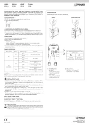
Vimar 01550.1 Bruksanvisning
Läs gratis den bruksanvisning för Vimar 01550.1 (4 sidor) i kategorin Dimmer. Guiden har ansetts hjälpsam av 40 personer och har ett genomsnittsbetyg på 4.4 stjärnor baserat på 20.5 recensioner. Har du en fråga om Vimar 01550.1 eller vill du ställa frågor till andra användare av produkten? Ställ en fråga
Sida 1/4

Regolatore 4 uscite a relè NO 16 A 250 V~, 4 uscite 0/1-10 V, pulsanti per comando
locale, standard KNX Secure, installazione su guida DIN (60715 TH35), occupa 8
moduli da 17,5 mm.
Il dispositivo consente la dimmerazione a 1-10V di 4 apparecchi con un assorbimento massimo di
100 mA per canale.
CARATTERISTICHE.
• Tensione di alimentazione: BUS 29 V d.c.
• Consumo sul bus: 12 mA
• Tensione di uscita: 1-10 V (max. 100 mA/canale)
• Uscite: 4 canali commutazione/dimmerazione
• Collegamenti: morsetti a vite, 2x2,5 mm
2
• Temperatura di funzionamento: -5 °C - + 45 °C (uso interno)
• Umidità relativa (punto di rugiada escluso): < 93 %
• Grado di protezione: IP20
Distanza massima tra il dispositivo e il carico collegato: 70 m (utilizzare cavi con sezione 1 mm²)
Montaggio
Il regolatore può essere montato in distributori o in piccoli quadri elettrici per il fissaggio rapido su guide
di supporto da 35 mm a norme DIN EN 60715. Deve essere assicurata l‘accessibilità all‘apparecchio
a scopo di controllo, ispezione, manutenzione e riparazione.
FUNZIONAMENTO.
• Comando manuale (regolazione e ON/OFF) delle uscite.
• Commutazione/dimmerazione.
• Funzione luce scale.
• Configurazione della modalità di funzionamento normale/temporizzatore.
• Configurazione di scenari fino ad un massimo di 15.
• Configurazione del comportamento alla ricezione del comando ON/dimmerazione.
• Configurazione dei valori di preset di dimmerazione.
• Possibilità di scegliere il comportamento al ripristino della tensione sul bus.
SIGNIFICATO DEI LED.
• LED programmazione:
- rosso fisso = assegnazione dell‘indirizzo durante la fase di configurazione;
- verde lampeggiante = normale funzionamento del dispositivo.
• LED di stato: arancione fisso quando l‘uscita è attiva.
CONFIGURAZIONE.
La configurazione del dispositivo e dei relativi parametri avviene mediante il software ETS.
Per avviare la configurazione del dispositivo e assegnare l’indirizzo fisico premere il pulsante di confi-
gurazione; il LED rosso sarà acceso fisso durante tutta l’operazione.
Tutti i database ETS aggiornati sono scaricabili dalla sezione “Software” del sito www.vimar.com.
GESTIONE MANUALE.
Il regolatore consente la regolazione e la commutazione manuale delle utenze.
• Tasto di comando 1-10 V: regolazione (incremento/decremento) in modalità toggle.
• Switch:
- posizione 1 = attivazione del carico e contatto relè chiuso;
- posizione 0 = disattivazione del carico e contatto relè aperto.
REGOLE DI INSTALLAZIONE.
• L’installazione deve essere effettuata da personale qualificato con l’osservanza delle disposizioni
regolanti l’installazione del materiale elettrico in vigore nel paese dove i prodotti sono installati.
• Gli interventi sulla rete elettrica a 230 V devono essere effettuati esclusivamente da personale
specializzato.
• Prima di effettuare l’installazione togliere la tensione di rete.
• Gli apparecchi sporchi possono essere puliti con un panno asciutto o leggermente inumidito di acqua
saponata. Non utilizzare in nessun caso sostanze caustiche o solventi.
IMPORTANTE:
Per evitare tensioni di contatto pericolose dovute all‘alimentazione di ritorno di diverse linee esterne,
in caso di espansione o di modifica del collegamento elettronico è necessario effettuare una disinser-
zione onnipolare
CONFORMITA’ NORMATIVA.
Direttiva BT. Direttiva EMC. Direttiva RoHS. Norme EN IEC 60669-2-1, EN IEC 63044, EN IEC 63000.
Regolamento REACh (UE) n. 1907/2006 – art.33. Il prodotto potrebbe contenere tracce di piombo.
RAEE - Informazione agli utilizzatori
Il simbolo del cassonetto barrato riportato sull’apparecchiatura o sulla sua confezione indica che il prodotto alla fine della propria vita
utile deve essere raccolto separatamente dagli altri rifiuti. L’utente dovrà, pertanto, conferire l’apparecchiatura giunta a fine vita agli
idonei centri comunali di raccolta differenziata dei rifiuti elettrotecnici ed elettronici. In alternativa alla gestione autonoma, è possibile
consegnare gratuitamente l’apparecchiatura che si desidera smaltire al distributore, al momento dell’acquisto di una nuova apparec-
chiatura di tipo equivalente. Presso i distributori di prodotti elettronici con superficie di vendita di almeno 400 m
2
è inoltre possibile
consegnare gratuitamente, senza obbligo di acquisto, i prodotti elettronici da smaltire con dimensioni inferiori a 25 cm. L’adeguata rac-
colta differenziata per l’avvio successivo dell’apparecchiatura dismessa al riciclaggio, al trattamento e allo smaltimento ambientalmente
compatibile contribuisce ad evitare possibili effetti negativi sull’ambiente e sulla salute e favorisce il reimpiego e/o riciclo dei materiali di
cui è composta l’apparecchiatura.
Dimmer with 4 NO relay outputs 16 A 250 V~, 4 outputs 0/1-10 V, push buttons
for local control, KNX standard, installation on DIN rails (60715 TH35), occupies 8
modules size 17.5 mm.
The device enables the dimming at 1-10V of 4 devices with a maximum absorption of 100 mA per
channel.
CHARACTERISTICS.
• Supply voltage: BUS 29 V DC
• Consumption on the bus: 12 mA
• Output voltage: 1-10 V (max. 100 mA/channel)
• Outputs: 4 switching/dimming channels
• Connections: screw terminals, 2x2.5 mm
2
• Operating temperature: -5 °C - + 45 °C (indoor use)
• Relative humidity (excluding dewpoint): < 93 %
• Protection degree: IP20
Maximum distance between the device and the load connected: 70 m (use cables with a cross
section of 1 mm²)
Mounting
The dimmer can be mounted in distributors or in small electrical cabinets for quick fixing on 35 mm
rails to DIN EN 60715 standards. Access to the device must be ensured for control, inspection,
maintenance and repair.
OPERATION.
• Manual control (adjustment and ON/OFF) of outputs.
• Switching/dimming.
• Stair light function.
• Configuration of the normal/timed operating modes.
• Configuration of up to a maximum of 15 scenarios.
• Configuration of behaviour upon receipt of the On/dimming control.
• Configuration of the dimming preset values.
• Possibility of selecting the behaviour when the voltage on the bus is restored.
MEANING OF THE LEDS.
• Programming LED:
- red permanently lit = address being assigned during configuration;
- flashing green = normal device operation.
• Status LED: orange permanently lit when the output is active.
CONFIGURATION.
Device and related parameter configuration occurs using the ETS software.
To launch the configuration of the device and assign the physical address, press the configuration push
button; the red LED will be permanently lit throughout the entire operation.
All the updated ETS databases can be downloaded from the “Software” section of the www.
vimar.com website.
MANUAL MANAGEMENT.
The dimmer enables the manual switching and adjustment of utilities.
• Control button 1-10 V: adjustment (increase/decrease) in toggle mode.
• Switch:
- position 1 = load activation and relay contact closed;
- position 0 = load deactivation and relay contact open.
INSTALLATION RULES.
• Installation must be carried out by qualified persons in compliance with the current regulations
regarding the installation of electrical equipment in the country where the products are installed.
• Work on the 230 V electricity mains must only be performed by skilled personnel.
• Cut off the mains voltage before performing installation.
• Dirty devices can be cleaned with a dry cloth or a cloth dampened with soapy water. Never, under
any circumstances, use solvents or caustic substances.
IMPORTANT:
To avoid dangerous contact voltages due to the return power supply of different external lines, when
expanding or modifying the electronic connection, an omnipolar disconnection is necessary.
REGULATORY COMPLIANCE.
BT directive. EMC directive. RoHS directive. Standards EN IEC 60669-2-1, EN IEC 63044, EN IEC 63000.
REACH (EU) Regulation no. 1907/2006 – Art.33. The product may contain traces of lead.
WEEE - User information
The crossed bin symbol on the appliance or on its packaging indicates that the product at the end of its life must be collected
separately from other waste. The user must therefore hand the equipment at the end of its life cycle over to the appropriate municipal
centres for the differentiated collection of electrical and electronic waste. As an alternative to independent management, you can
deliver the equipment you want to dispose of free of charge to the distributor when purchasing a new appliance of an equivalent type.
You can also deliver electronic products to be disposed of that are smaller than 25 cm for free, with no obligation to purchase, to
electronics distributors with a sales area of at least 400 m
2
. Proper sorted waste collection for subsequent recycling, processing and
environmentally conscious disposal of the old equipment helps to prevent any possible negative impact on the environment and human
health while promoting the practice of reusing and/or recycling materials used in manufacture.
Variateur 4 sorties à relais NO 16 A 250 V~, 4 sorties 0/1-10 V, poussoirs pour
commande locale, standard KNX Secure, installation sur rail DIN (60715 TH35),
occupe 8 modules de 17,5 mm.
Le dispositif permet la variation à 1-10V de 4 appareils avec une absorption maximale de 100 mA
par canal.
CARACTÉRISTIQUES.
• Tension d'alimentation : BUS 29 Vcc
• Consommation du bus : 12 mA
• Tension de sortie : 1-10 V (maxi 100 mA/canal)
• Sorties : 4 canaux commutation/variation
• Connexions : bornes à vis, 2x2,5 mm
2
• Température de fonctionnement : -5 °C - +45 °C (usage intérieur)
• Humidité relative (point de rosée non compris) : < 93 %
• Indice de protection : IP20
Distance maximale entre le dispositif et la charge connectée : 70 m (utiliser des câbles d’une
section de 1 mm²)
Montage
Le variateur peut être installé sur des distributeurs ou de petits boîtiers électriques pour la fixation
rapide sur des rails de support de 35 mm conformes aux normes DIN EN 60715. L'appareil doit rester
accessible pour le contrôle, l'inspection, la maintenance et la réparation.
FONCTIONNEMENT.
• Commande manuelle (réglage et ON/OFF) des sorties.
• Commutation/variation.
• Fonction éclairage escalier.
• Configuration du mode de fonctionnement normal/temporisé.
Viale Vicenza, 14
36063 Marostica VI - Italy
www.vimar.com
49402006A0 01 2409
01550.1
WELL-CONTACT PLUS
Produktspecifikationer
| Varumärke: | Vimar |
| Kategori: | Dimmer |
| Modell: | 01550.1 |
Behöver du hjälp?
Om du behöver hjälp med Vimar 01550.1 ställ en fråga nedan och andra användare kommer att svara dig
Dimmer Vimar Manualer
10 September 2025
10 September 2025
10 September 2025
10 September 2025
9 September 2025
25 Augusti 2025
24 Augusti 2025
24 Augusti 2025
24 Augusti 2025
24 Augusti 2025
Dimmer Manualer
- Elro
- Intertechno
- Hager
- Ltech
- VAMA
- Eurolite
- Mercury
- Bearware
- Trust
- Merten
- Legrand
- Gira
- Schneider Electric
- Handson
- Crestron
Nyaste Dimmer Manualer
12 September 2025
12 September 2025
30 Augusti 2025

27 Augusti 2025

27 Augusti 2025
27 Augusti 2025
19 Augusti 2025
19 Augusti 2025
18 Augusti 2025
18 Augusti 2025