Apc SYNX-980214 Bruksanvisning
Apc Inte kategoriserad SYNX-980214
Läs gratis den bruksanvisning för Apc SYNX-980214 (1 sidor) i kategorin Inte kategoriserad. Guiden har ansetts hjälpsam av 43 personer och har ett genomsnittsbetyg på 4.5 stjärnor baserat på 3 recensioner. Har du en fråga om Apc SYNX-980214 eller vill du ställa frågor till andra användare av produkten? Ställ en fråga
Sida 1/1
Modular Data Line
Installation Manual
Surge Protection System
Thank you for purchasing APC’s Modular Data Line Surge Protection System. Please fill out the supplied
Warranty Registration Card or an on-line Product Warranty Registration form at www.apc.com.
If the device arrived damaged, notify the carrier.
If the device requires service, do not return it to the dealer. The following steps should
be taken:
1.Go to http://www.apc.com/support/.
2.Have the model number, serial number and date of purchase available. Be
prepared to troubleshoot the problem with an APC Technical Support
representative. If this is not successful, APC will issue a Return Merchandise
Authorization (RMA) number and a shipping address.
APC warrants its products to be free from defects in materials and workmanship under
normal use and service for the lifetime of the original purchaser. Its obligation under
this warranty is limited to repairing or replacing, at its sole option, any such defective
products. To obtain service under warranty you must obtain a Returned Material
Authorization (RMA) number from APC or an APC Service Center. Product must be
returned to APC or an APC Service Center with transportation charges prepaid and
must be accompanied by a brief description of the problem and proof of date and place
of purchase.
This warranty applies only to the original purchaser.
For information please call APC Customer Service Center at:
American Power Conversion1-401-789-5735 or 1-800-800-4APC (4272)
132 Fairgrounds Roadhttp://www.apc.com/support or
West Kingston, RI 01892 USAesupport@apcc.com
Service
Limited Lifetime Warranty
Customer Service / Technical Support
990-1383 12/02 Copyright © 2002 American Power Conversion. All rights reserved.
Model: PNETR5
ItemSpecification
Lines ProtectedPins 1-8 on RJ-45 connector
Mode of ProtectionBetween send/receive pairs and
any signal line to ground.
Peak Voltage± 2,000 Volts, 1.2/ 50 µs test
waveform
Peak Current150 Amps, 8/ 20 µs test
waveform
Breakover (turn on)
Voltage
60 V peak nominal between send/
receive pairs
IsolationCompliant with the applicable
safety isolation requirements of
standards IEEE 802.3 or IEEE
802.5
Response Time<1ns
Agency ApprovalsUL 497B recognized
Model: PTEL2R
ItemSpecification
Lines ProtectedPins 3&4 and 5&6 on RJ-45
connector; accepts RJ-45 &
RJ-11 plugs
Mode of ProtectionMetallic (Tip - Ring) and
longitudinal (Tip + Ring -
Ground)
Peak Voltage± 2,000 Volts, 1.2/50 µs test
waveform
Peak Current150 Amps, 8/ 20 µs test
waveform
Breakover (turn on)
Voltage
270 V peak nominal between
tip and ring
Overload ProtectionSolid-state self-resetting fuse
Response Time<1 ns
Agency ApprovalsUL 497A recognized
Model: P232R
Note: The PRM24 Chassis is listed to UL 60950 and VDE
approved.
ItemSpecification
Lines ProtectedPins 1-8 on RJ-45 connector
Mode of ProtectionBetween send/receive pairs
and any signal line to ground
Peak Voltage± 2,000 Volts, 1.2/50 µs test
waveform
Peak Current150 Amps, 8/ 20 µs test
waveform
Breakover (turn on)
Voltage
19 V nominal between send/
receive pairs
Response Time<1 ns
Module Information
Federal Communications Commission (FCC) Notice
This equipment contains an FCC compliant RJ-45 modular jack. It is designed to be connected to the telephone
network or premises wiring using compatible modular plugs and cabling which comply with the requirements
of FCC Part 68 rules. The Ringer Equivalence Number (REN) is used to determine the number of devices
which may be connected to the telephone line. An excessive REN may cause the equipment to not ring in
response to an incoming call. In most areas, the sum of RENs of all equipment on a line should not exceed five
(5).
In the unlikely event that this equipment causes harm to the telephone network, the telephone company can
temporarily disconnect your service. The telephone company will try to warn you in advance of any such
disconnection, but if advance notice isn’t practical, it may disconnect the service first and notify you as soon as
possible afterwards. In the event such a disconnection is deemed necessary, you will be advised of your right to
file a complaint with the FCC.
From time to time, the telephone company may make changes in its facilities, equipment, or operations which
could affect the operation of connected equipment. If this occurs, the telephone company is required to provide
you with advance notice so you can make the modifications necessary to maintain uninterrupted service. This
product is not serviceable by the user.
6
3
4
8
To Equipment
to be Protected
From
Signal
Source
1
7
5
2
9
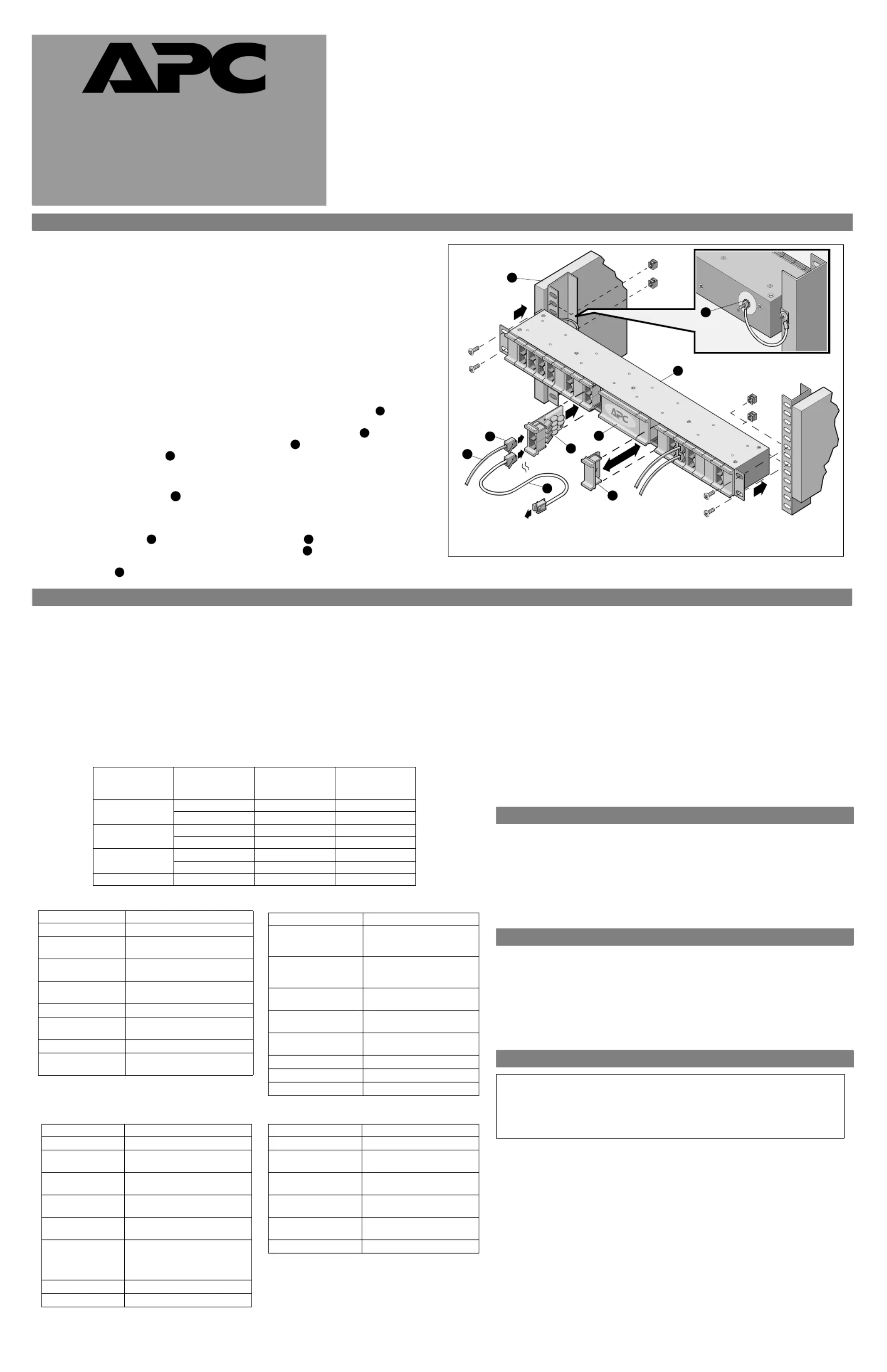
Figure 1. Typical Installation
w
w
w
.apc.com
®
Model: PDIGTR
ItemSpecification
Lines ProtectedPins 1-8 on RJ-45 connector
Mode of ProtectionBetween send/receive pairs and
any signal line to ground
Peak Voltage± 2,000 Volts, 1.2/50 µs test
waveform
Peak Current100A (max with 10X 1000 µs
waveform
Operating Current150 mA Maximum
Breakover (turn on)
Voltage
Metallic (line-to-line): 60VDC
Nominal
Response Time<1 ns
Regulatory Approval /
Classification
UL 497A recognized, FCC
APC’s Modular Data Line Surge Protection System consists of the PRM24 Chassis, mounting hardware, ground wire, and
associated data line modules (PNETR5 for Network Protection, PTEL2R for Analog Telephone Protection, P232R for RS232
Protection,and PDIGTR for Digital Telephone Protection). The chassis was designed for use in any EIA-standard 19-inch (48.2
cm) wide equipment rack or enclosure.
This manual provides basic information necessary to install the chassis and associated modules in a rack or enclosure.
Procedures provided in this document are not intended to supercede local standards or codes. Reference the
Telecommunications Industries Association and Electronic Industries Alliance publication “Commercial Building,
Telecommunications Cabling Standard, General Requirements” (document number TIA/EIA-568-B.1-2001) to ensure proper
installation of system wiring.
Model PNETR5 (Network Protection)
The PNETR5 module will protect the port of a Network Interface Card, hub or other local area network
(LAN) equipment from damage caused by lightning-generated electrical transients. This module provides
surge protection for 10Base-T, 100Base-T4, 100Base-TX, 100VG or Token Ring Type 3 UTP port (RJ-45),
and VOIP applications. PNETR5 complies with applicable ISO/IEC Standard 8802-3 (IEEE 802.3) or 8802-
5 (IEEE 802.5) requirements.
In applications where the network data transmission rate is high, insertion loss introduced by in-line devices
becomes a significant consideration where cable lengths are particularly long. At the 100 Mbp/s data
transmission rate, there is a small insertion loss introduced by the PNETR5. Use Table 1 to approximate the
insertion loss based on cable length effectively introduced by the PNETR5 by installed cable Category level
or type. The ISO/IEC 8802-3 standard specifies a maximum UTP cable length of 100 meters per segment at
10/100 Mbp/s. For Thinnet, the maximum cable length is 185 meters (607 feet).
Table 1
EIA/TIA 568
Category or Cable
Type
Frequency
(MHz)
Attenuation
(db/100m)
Equivalent Cable
Length (m)
3109.81.0 (3.3 ft)
1613.11.10 (3.5 ft)
4107.21.4 (4.5 ft)
168.91.6 (5.2 ft)
5106.61.5 (4.9 ft)
168.21.7 (5.6 ft)
51002212.5 (41 ft)
Model PTEL2R (Analog Telephone Protection)
The PTEL2R module protects analog telephones, ADSL, ISDN2, voice mail and
automated answering systems, fax machines and modems from damage caused by
lightning-generated electrical transients. Each PTEL2R protects up to 2 lines.
Warning: Disconnect module wires before removing any module. Do not put fingers
or any object inside the chassis.
Model P232R (RS232 Protection)
The P232R module is for use with RS232 communication equipment (RS232
multiports, asynchronous multiplexers, asynchronous printer spoolers, etc.)
comprised of unshielded, twisted-pair wiring with RJ-45 connectors. It protects up to
four ports per unit.
Model PDIGTR (Digital Telephone Protection)
The PDIGTR module is only for use in T1, CSU, DSU, ISDN, DDS and Digital
Leased Line telecommunication equipment, TNV-1 or SELV circuits only.
General Installation
Safety
Caution: This equipment is intended to be used in a restricted access area and should only be
worked on by qualified service personal.
Please read and save these instructions and observe the following safety precautions.
•Use the system in a protected environment only.
•Never install telephone wiring during a lightning storm.
•Follow the installation instructions carefully. The current limiting feature in this product
could be rendered inoperable if the product is improperly installed.
Other Considerations
•Do not install this device in an environment where the operating temperature exceeds 0 to
40
o
C (32 to 104
o
F).
•Do not install this device where the relative humidity exceeds 95%, non-condensing.
•Do not store this device in an environment that exceeds 0 to 45
o
C (32 to 113
o
F).
Chassis Installation and Grounding
APC recommends that the ProtectNET
TM
Data Line Surge Protection chassis (, Figure 1)
PRM24, be installed using the mounting hardware provided with the chassis. Additionally, the
chassis must be connected to a proper protective earth ground. A ground stud is provided on
the back of the chassis. Ensure the mounting rack or enclosure is connected to a proper ground.
Install the chassis and modules as shown in the illustration below.
Module Installation
The system chassis is designed to accomodate up to 24 data line modules. To install a module,
remove one of the blank panels by pulling it straight out from the chassis. Align the module
with the groove in the chassis, and slide the module fully into the chassis.
Cable Installation
To install a data line cable , connect the input RJ-45 connector to the signal source and then
to the upper connector on the module. Connect a data line cable from the lower connector on
the module to the equipment to be protected. Note: To accomodate 24 modules, the four-wide
center blank panel must be removed.
1
2
3
4
5
67
8
9
Ground
Stud / Wire
Produktspecifikationer
| Varumärke: | Apc |
| Kategori: | Inte kategoriserad |
| Modell: | SYNX-980214 |
Behöver du hjälp?
Om du behöver hjälp med Apc SYNX-980214 ställ en fråga nedan och andra användare kommer att svara dig
Inte kategoriserad Apc Manualer

9 April 2025
29 Mars 2025
29 Mars 2025
29 Mars 2025
28 Januari 2025
11 December 2024
11 December 2024
5 December 2024
15 Oktober 2024
14 Oktober 2024
Inte kategoriserad Manualer
Nyaste Inte kategoriserad Manualer
9 April 2025
9 April 2025
9 April 2025
9 April 2025
9 April 2025
9 April 2025
9 April 2025
9 April 2025
9 April 2025
9 April 2025