Groen TS/10 Bruksanvisning
Groen
ej kategoriserat
TS/10
Läs gratis den bruksanvisning för Groen TS/10 (26 sidor) i kategorin ej kategoriserat. Guiden har ansetts hjälpsam av 3 personer och har ett genomsnittsbetyg på 4.5 stjärnor baserat på 2 recensioner. Har du en fråga om Groen TS/10 eller vill du ställa frågor till andra användare av produkten? Ställ en fråga
Sida 1/26

OPERATOR MANUAL
IMPORTANT INFORMATION, KEEP FOR OPERATOR
888-994-7636, fax 888-864-7636
groen.com
THIS MANUAL MUST BE RETAINED FOR FUTURE REFERENCE. READ,
UNDERSTAND AND FOLLOW THE INSTRUCTIONS AND WARNINGS CONTAINED
IN THIS MANUAL.
FOR YOUR SAFETY Instructions to be followed in the event user smells gas.
This information shall be obtained by consulting your local gas supplier. As
a minimum, turn off the gas and call your gas company and your authorized
service agent. Evacuate all personnel from the area.
WARNING Improper installation, adjustment, alteration, service or
maintenance can cause property damage, injury or death. Read the
installation, operating and maintenance instructions thoroughly before
installing or servicing this equipment.
NOTIFY CARRIER OF DAMAGE AT ONCE It is the responsibility of the
consignee to inspect the container upon receipt of same and to determine
the possibility of any damage, including concealed damage. Groen suggests
that if you are suspicious of damage to make a notation on the delivery
receipt. It will be the responsibility of the consignee to le a claim with the
carrier. We recommend that you do so at once.
Manufacture Service/Questions 888-994-7636.
PART NUMBER 174844, REV. H (03/25)
This manual provides information for:
STEAM JACKETED KETTLE
MODELS TDH(C)-20/24/40/48 (C,A,C2T™)
DOMESTIC
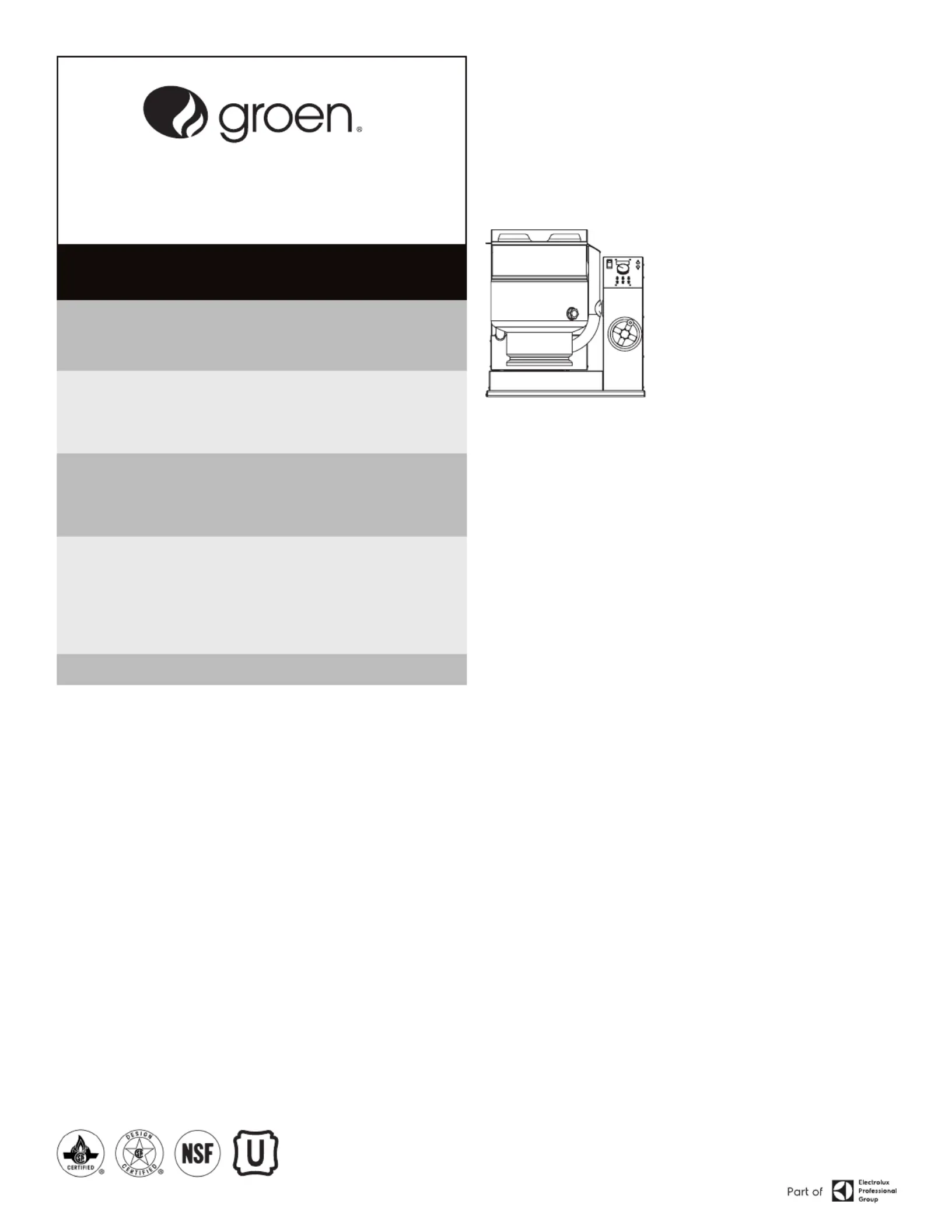
EQUIPMENT DESCRIPTION
TDH and TDHC models are stainless steel, steam-jacketed, table top mounted
kettles with a self-contained, gas heated steam source. The TDHC has a crank tilt
hand wheel, and the TDH has a handle that allows the operator to manually tilt the
kettle. The kettle body is welded into one solid piece and furnished with a rein-
forced rim and welded-in “buttery” shaped pouring lip. The interior of the kettle
is polished to a 180 emery grit nish, and the exterior is given a bright high buff
nish. The unit is A.S.M.E. shop inspected and registered with the National Board
for a design pressure of 50 PSIG.
The self-contained steam source is heated by propane or natural gas and is
equipped with electronic ignition. Charged at the factory with chemically pure wa-
ter containing rust inhibitors, the steam source provides kettle temperatures of
150ºF to approximately 295ºF.
Controls for the TDHC unit include a crank tilt handwheel, thermostat, pressure
gauge, pressure relief valve, low water cut-off, On/Off switch, indicator lamp, gas
regulator valve, and water level sight glass. Controls for the TDH are the same as
the above, with the exception of the crank tilt hand wheel.
The gas supply shuts off automatically when the kettle is tilted.
The unit must be specied for use with natural gas or propane. For other gas types,
consult factory. Service connections are required for gas and 115V electricity.
Options available include:
1. One-piece, Lift-off cover
2. Holder for Lift-off Cover
3. Basket insert
4. Rice Strainer
5. Stand that supports the unit and holds a pan in position for lling
6. Water ll swing faucet
7. 316 stainless steel interior (must be indicated on initial order)
REFERENCES
CSA INTERNATIONAL
8501 East Pleasant Valley Road
Cleveland, Ohio 44131
NSF INTERNATIONAL
798 N. Dixboro Rd.
P.O. Box 130140
Ann Arbor, Michigan 48113-0140
UNDERWRITERS LABORATORIES, INC.
333 Pngsten Road
Northbrook, Illinois 60062
KLENZADE SALES CENTER ECOLAB, Inc.
370 Wabasha
St. Paul, Minnesota 55102
NATIONAL FIRE PROTECTION ASSOCIATION
60 Battery March Park
Quincy, Massachusetts 02269
NFPA/54 -Installation Gas Appliances &
Piping
NFPA/70 - The National Electric Code
ZEP MANUFACTURING COMPANY
1310-T Seaboard Industrial Boulevard
Atlanta, Georgia 30318
Information contained in this document is known to be current and accurate at the time of printing/creation. Reference our product line
website for the most updated product information and specications. © 2025 Electrolux Professional, Inc. All Rights Reserved.

2 OM-TDH(C)-20/24/40/48 (C,A,C2T™) Domestic
PERFORMANCE DATA
Model Firing Rate, BTU/hr
TDH-20, TDHC-20, TDH-24, TDHC-24 31,000
TDH-40, TDHC-40, TDH-48, TDHC-48 52,000
Model
Kettle
Capacity
Jacket
Capacity
Kettle
Body
Diameter
Kettle
Body
Depth
Base
Width
Base
Depth
TDH-20
(C,A,C2T)
TDHC-20
(C,A,C2T)
5 Gal.
(20 Qt.)
6 Qt
14
inches
11
inches
28
inches
24
inches
19 liter 5.7 liter 356 mm 279 mm 711 mm 610 mm
TDH-24
(C,A,C2T)
TDHC-24
(C,A,C2T)
6-Gal.
(24 Qt.)
6 Qt
14
inches
12-1/2
inches
28
inches
24
inches
23 liter 5.7 liter 356 mm 318 mm 711 mm 610 mm
TDH-40
(C,A,C2T)
TDHC-40
(C,A,C2T)
10 Gal.
(40 Qt.)
12 Qt
16-1/2
inches
14-1/2
inches
28
inches
26-3/4
inches
38 liter 11.4 liter 419 mm 368 mm 711 mm 680 mm
TDH-48
(C,A,C2T)
TDHC-48
(C,A,C2T)
12 Gal.
(48 Qt.)
12 Qt
16-1/2
inches
16
inches
28
inches
26-3/4
inches
45 liter 11.4 liter 419 mm 406 mm 711 mm 680 mm
IMPORTANT - READ FIRST - IMPORTANT
WARNING: FAILURE TO DISCONNECT POWER BEFORE SERVICING COULD RESULT IN
ELECTROCUTION AND DEATH.
WARNING: IMPROPER INSTALLATION, ADJUSTMENT, ALTERATION, SERVICE OR
MAINTENANCE CAN CAUSE PROPERTY DAMAGE, INJURY OR DEATH. READ THE
INSTALLATION, OPERATING AND MAINTENANCE INSTRUCTIONS THOROUGHLY
BEFORE INSTALLING OR SERVICING THIS EQUIPMENT.
WARNING: THE UNIT MUST BE INSTALLED BY PERSONNEL QUALIFIED TO WORK WITH GAS,
ELECTRICITY AND PLUMBING. UNIT MUST BE INSTALLED IN ACCORDANCE WITH
ALL APPLICABLE CODES.
WARNING: DO NOT ATTACH THE UNIT TO A TYPE “B” VENT. IT COULD CAUSE FIRE OR
PROPERTY DAMAGE.
WARNING: DO NOT CONNECT ANY PIPING TO THE PRESSURE RELIEF VALVE. IT MUST BE
FREE TO VENT STEAM AS NEEDED. TO AVOID BURNS FROM THE VENTED STEAM
THE VALVE DISCHARGE SHOULD POINT DOWNWARD.
DANGER: ELECTRICALLY GROUND THE UNIT AT THE TERMINAL PROVIDED. FAILURE TO
GROUND THE UNIT COULD RESULT IN ELECTROCUTION AND DEATH.
CAUTION: BE SURE ALL OPERATORS READ, UNDERSTAND AND FOLLOW THE OPERATING
INSTRUCTIONS, CAUTIONS AND SAFETY INSTRUCTIONS CONTAINED IN THIS
MANUAL.
CAUTION: DO NOT OVERFILL THE KETTLE WHEN COOKING, HOLDING OR CLEANING. KEEP
LIQUIDS A MINIMUM OF 2-3” (5-8 CM) BELOW THE KETTLE BODY RIM TO ALLOW
CLEARANCE FOR STIRRING, BOILING AND SAFE TRANSFER OF PRODUCT.
CAUTION: KEEP FLOORS IN FRONT OF KETTLE WORK AREA CLEAN AND DRY. IF SPILLS
OCCUR, CLEAN IMMEDIATELY TO AVOID SLIPS OR FALLS.
WARNING: KEEP WATER AND SOLUTIONS OUT OF CONTROLS AND BURNERS. NEVER USE A
HIGH PRESSURE HOSE TO CLEAN KETTLE SURFACES.
CAUTION: MOST CLEANERS ARE HARMFUL TO THE SKIN, EYES, MUCOUS MEMBRANES
AND CLOTHING. TAKE PRECAUTIONS: WEAR RUBBER GLOVES, GOGGLES OR
FACE SHIELD AND PROTECTIVE CLOTHING. CAREFULLY READ WARNINGS AND
FOLLOW DIRECTIONS ON CLEANER LABELS.
WARNING: DO NOT STAND ON OR APPLY UNNECESSARY WEIGHT OR PRESSURE ON THE KETTLE
FRONT OR POURING LIP. THIS COULD RESULT IN THE OVERLOAD AND FAILURE OF
THE TILT MECHANISM, AND POSSIBLE SERIOUS INJURY AND BURNS TO THE
OPERATOR AND OTHERS.
NOTICE: NEVER LEAVE A SANITIZER IN CONTACT WITH STAINLESS STEEL SURFACES LONGER
THAN 30 MINUTES. LONGER CONTACT CAN CAUSE CORROSION.
WARNING: FAILURE TO PERIODICALLY CHECK PRESSURE RELIEF VALVE OPERATION COULD
RESULT IN PERSONAL INJURY AND/OR DAMAGE TO EQUIPMENT.
WARNING: WHEN TESTING, AVOID EXPOSURE TO THE STEAM BLOWING OUT OF THE PRESSURE
RELIEF VALVE. DIRECT CONTACT COULD RESULT IN SEVERE BURNS.
WARNING: TO AVOID INJURY, READ AND FOLLOW ALL PRECAUTIONS STATED ON THE LABEL OF
THE WATER TREATMENT COMPOUND.
WARNING: BEFORE REPLACING ANY PARTS, DISCONNECT THE UNIT FROM THE ELECTRIC
POWER SUPPLY AND CLOSE THE MAIN GAS VALVE. ALLOW FIVE MINUTES FOR GAS
TO VENT.
CAUTION: USE OF ANY REPLACEMENT PARTS OTHER THAN THOSE SUPPLIED BY THE
MANUFACTURER OR AUTHORIZED DISTRIBUTORS CAN CAUSE INJURY TO THE
OPERATOR AND DAMAGE TO THE EQUIPMENT AND WILL VOID ALL WARRANTIES.
WARNING: KEEP AREA AROUND KETTLE FREE AND CLEAR OF ALL COMBUSTIBLE MATERIALS.
FAILURE TO DO SO COULD RESULT IN FIRE OR PROPERTY DAMAGE.
CAUTION: HEATING AN EMPTY KETTLE MAY CAUSE THE RELEASE OF STEAM FROM THE
PRESSURE RELIEF VALVE.
IMPORTANT: SERVICE PERFORMED BY OTHER THAN FACTORY AUTHORIZED PERSONNEL WILL
VOID ALL WARRANTIES.
NOTICE: IT IS RECOMMENDED THAT AN INSTANT-READ THERMOMETER BE USED TO
CHECK THE INTERNAL TEMPERATURE THROUGHOUT THE COOKING PROCESS
AND AFTER THE COOKING PROCESS HAS BEEN COMPLETED TO ENSURE THE
FOOD HAS BEEN COOKED SUFFICIENTLY.
INSPECTION & UNPACKING
CAUTION: SHIPPING STRAPS ARE UNDER TENSION AND CAN SNAP BACK WHEN CUT.
TAKE CARE TO AVOID PERSONAL INJURY OR DAMAGE TO THE UNIT BY
STAPLES LEFT IN THE WALLS OF THE CARTON.
CAUTION: THIS UNIT WEIGHS BETWEEN 214 AND 240 POUNDS (98 TO 109 KG)
DEPENDING ON SIZE. INSTALLER SHOULD USE PROPER EQUIPMENT TO
LIFT SAFELY.
The unit arrives completely assembled, except for the tilting handle on hand tilt
models which is shipped inside the kettle. The unit is strapped on a skid and in
a heavy carton. Inspect the carton carefully for damage. Open the container and
check the unit for hidden damage. Report shipping damage or shipment errors to
the delivery agent.
Write down the model number, serial number, and installation date for your unit at
the top of the Service Log at the end of this manual. Keep this manual with the unit.
To remove the kettle from the box, cut any straps from around the box. Detach the
box sides from the skid. Pull the box up off the unit, taking care to avoid damage
or injury from any staples left in the box walls. When installation is to begin, cut
the straps holding the kettle on the skid, and lift the kettle straight up off the skid.
Examine the packing materials to make sure no loose parts are discarded with the
materials. On hand tilt models, the tilting handle may be screwed into its socket.
Attach handle to the kettle on left side or right side as shown below.

3 OM-TDH(C)-20/24/40/48 (C,A,C2T™) Domestic
INSTALLATION
WARNING: THE UNIT MUST BE INSTALLED BY PERSONNEL WHO ARE QUALIFIED TO
WORK WITH GAS, ELECTRICITY AND PLUMBING. IMPROPER INSTALLATION
CAN CAUSE INJURY TO PERSONNEL AND/OR DAMAGE TO THE EQUIPMENT.
THE UNIT MUST BE INSTALLED IN ACCORDANCE WITH APPLICABLE CODES.
THE UNIT MUST BE INSTALLED BY A LICENSED PLUMBER OR GAS FITTER
WHEN INSTALLED WITHIN THE COMMONWEALTH OF MASSACHUSETTS.
DANGER: ELECTRICALLY GROUND THE UNIT AT THE TERMINAL PROVIDED. FAILURE
TO GROUND UNIT COULD RESULT IN ELECTROCUTION AND DEATH.
WARNING: THIS UNIT IS FOR COMMERCIAL USE. DO NOT USE HOME OR RESIDENTIAL
GRADE GAS CONNECTIONS. THEY DO NOT MEET GAS CODES AND COULD
BE HAZARDOUS.
For efcient performance the kettle must be installed in a well-ventilated
area. Items which might restrict or obstruct the ow of air for combustion and
ventilation must be removed. The area directly around the appliance must be free
of combustible materials.
1. Installation can be on a combustible or noncombustible oor. Clearances
should be per table below.
MINIMUM CLEARANCE FROM
COMBUSTIBLE WALLS
RECOMMENDED
CLEARANCES
Left Side 1 in. 1 in.
Right Side 0 in. 12-16 in. for servicing
Rear 1 in. 3 in. for faucet bracket
2. We recommends installation of the unit under a vent hood. The base must be
fastened to a working surface or stand.
3. Complete the piping to the gas service main using ½ inch IPS pipe or an
approved equivalent.
4. Provide 115 VAC, 60 cycle, 1 phase, 1 AMP electric service. Local codes and/
or The National Electrical Code should be observed in accordance with ANSI/
NFPA-70 latest edition. AN ELECTRICAL GROUND IS REQUIRED. The electrical
schematic is located on the inside of the service panel and in this manual.
5. Electrical connection to the unit must be water resistant sealtite conduit type
or equal and utilize the water resistant conduit tting provided on the unit.
6. The installation must conform with local codes or the American National
Standards Z223.1 - latest edition National Fuel Gas Code. The kettle should
be installed in an adequately ventilated room with provision for adequate air
supply. The best ventilation will employ a vent hood and exhaust fan with no
direct connection between the vent duct and the kettle ue. DO NOT obstruct
the ue or vent duct after installation.
7. Core probe storage bracket (C2T models only)
a. It is recommend that the core probe storage bracket be installed on the
control console. It is not recommend that the core probe storage bracket
be installed on the kettle body or cover.
b. To obtain proper adhesion, the bonding surface must be unied, clean and
dry. Clean the bonding surface with rubbing alcohol and allow the surface
to dry. Next rmly apply pressure to the storage bracket to help improve
bond strength. After application, the bond strength will increase as the
adhesive ows onto the surface. At room temperature, approximately
50% of the ultimate strength will be achieved after 20 minutes, 90% after
24 hours and 100% after 72 hours.
8. PRESSURE TEST WARNING
a. Test pressure exceeding ½ PSIG (3.45 kPa). During pressure testing of the
gas supply piping system at pressures exceeding ½ PSIG, the appliance
and its individual shutoff valve must be disconnected from the gas supply
piping system.
b. Test pressure equal to or less than ½ PSIG (3.45 kPa). During pressure
testing of the gas supply piping system at pressures equal to or less than
½ PSIG, the kettle must be isolated from the gas supply piping system by
closing its individual manual shutoff valve.
9. Adequate space for proper servicing and operation is required. DO NOT block
any air intake spacings to the combustion chamber or obstruct air ow.
10. After the kettle has been connected to the gas supply, check all gas joints for
leaks. A soap solution or other suitable gas leak detector should be used. Do
not use ame when checking for leaks.
11. Once the unit is anchored to a mounting surface, apply a small bead of silicone
caulk around the perimeter of the kettle base and seal the joint.
12. Make sure the water level is correct in the jacket, by conrming that the
level is near the middle of the sight glass. If the water level is low, follow the
instructions in Jacket Filling and Water Treatment in the Maintenance section
of this manual.
13. Check to be sure that the open end of the elbow on the outlet of the pressure
relief valve is directed downward. Be sure to read and follow the instructions
on the attached pressure relief valve tag.
INITIAL START-UP
IMPORTANT: BE SURE ALL OPERATORS READ, UNDERSTAND AND FOLLOW THE OPERATING
INSTRUCTIONS, CAUTIONS, AND SAFETY INSTRUCTIONS CONTAINED IN THIS
MANUAL.
WARNING: DO NOT STAND ON OR APPLY UNNECESSARY WEIGHT OR PRESSURE ON THE
KETTLE FRONT OR POURING LIP. THIS COULD RESULT IN THE OVERLOAD AND
FAILURE OF THE TILT MECHANISM, AND POSSIBLE SERIOUS INJURY AND
BURNS TO THE OPERATOR AND OTHERS.
The open end of the pressure relief valve
elbow must face downward.
Correct water level.
After the kettle has been installed, the installer should test to ensure that it is
operating correctly.
1. Remove literature and packing materials from inside and outside of the unit.
2. Add water to the kettle to a depth of at least one inch.
3. Make sure the supplies of gas and electric power are on.
4. Follow the “To Start Kettle Heating” instructions in the Operation section of
this manual. Begin heating the water at the highest thermostat setting. The
indicator light should come on and heating should continue until the water
boils.
5. To turn off the unit, follow “To Stop Kettle Heating” in the Operation Section of
this manual.
If the kettle functions as described, it is ready for use. If the unit does not operate
as designed, contact an authorized Service Agent.
Produktspecifikationer
Varumärke: | Groen |
Kategori: | ej kategoriserat |
Modell: | TS/10 |
Behöver du hjälp?
Om du behöver hjälp med Groen TS/10 ställ en fråga nedan och andra användare kommer att svara dig
ej kategoriserat Groen Manualer
1 September 2025
1 September 2025
31 Augusti 2025
ej kategoriserat Manualer
- LevelOne
- PCE Instruments
- GW Instek
- Hotone
- Sonel
- Natec
- Lasko
- Klein Tools
- Oklahoma Sound
- Honor
- Bender
- Corberó
- HP
- Laica
- Lindy
Nyaste ej kategoriserat Manualer
1 September 2025
1 September 2025
1 September 2025
1 September 2025
1 September 2025
1 September 2025
1 September 2025
1 September 2025
1 September 2025
1 September 2025