Sauermann CO2ST-S Bruksanvisning
Sauermann ej kategoriserat CO2ST-S
Läs gratis den bruksanvisning för Sauermann CO2ST-S (5 sidor) i kategorin ej kategoriserat. Guiden har ansetts hjälpsam av 11 personer och har ett genomsnittsbetyg på 4.8 stjärnor baserat på 2 recensioner. Har du en fråga om Sauermann CO2ST-S eller vill du ställa frågor till andra användare av produkten? Ställ en fråga
Sida 1/5
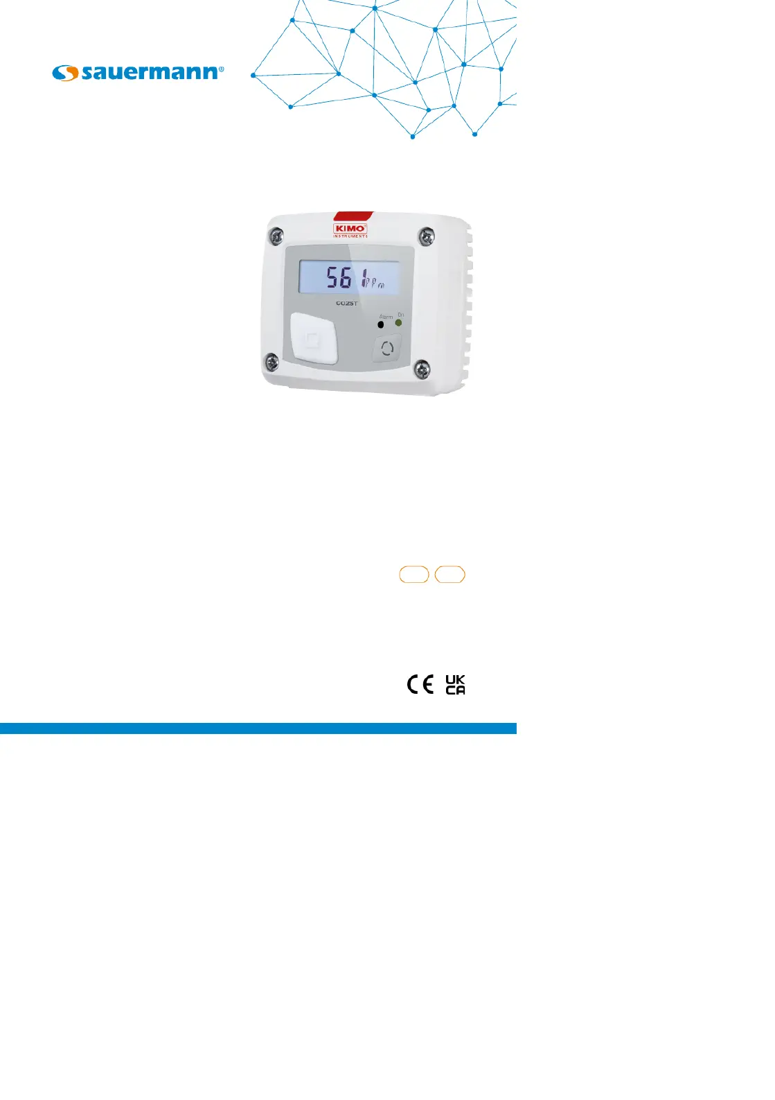
CO2ST-S
Quick Start Guide
ENFR
www.sauermanngroup.com
Produktspecifikationer
| Varumärke: | Sauermann |
| Kategori: | ej kategoriserat |
| Modell: | CO2ST-S |
Behöver du hjälp?
Om du behöver hjälp med Sauermann CO2ST-S ställ en fråga nedan och andra användare kommer att svara dig
ej kategoriserat Sauermann Manualer

20 September 2025
1 September 2025
28 Augusti 2025
27 Augusti 2025
27 Augusti 2025
27 Augusti 2025
27 Augusti 2025
27 Augusti 2025
27 Augusti 2025
27 Augusti 2025
ej kategoriserat Manualer
Nyaste ej kategoriserat Manualer
3 April 2026
3 April 2026
3 April 2026
3 April 2026
3 April 2026
3 April 2026
3 April 2026
3 April 2026
3 April 2026