Sauermann CP 210-R Bruksanvisning
Sauermann
ej kategoriserat
CP 210-R
Läs gratis den bruksanvisning för Sauermann CP 210-R (7 sidor) i kategorin ej kategoriserat. Guiden har ansetts hjälpsam av 2 personer och har ett genomsnittsbetyg på 4.7 stjärnor baserat på 1.5 recensioner. Har du en fråga om Sauermann CP 210-R eller vill du ställa frågor till andra användare av produkten? Ställ en fråga
Sida 1/7

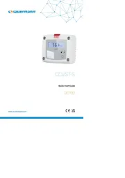
CP 210-R
Quick Start Guide
www.sauermanngroup.com
EN FR ES

English
Quick Start Guide
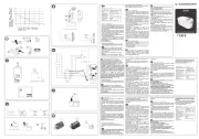
Differential pressure, air velocity, air ow and
temperature transmitter
General features
Features of the housing
CP 210-R
All dimensions are in mm
Two 4-wire analogue outputs
0-5/10 V or 0/4-20 mA
Range from ±100 to
±10000 Pa
(according
to model)
Air velocity and air
ow calculation
(optional)
with or without display
2 relay outputs
0-5 / 10 V
4-20 mA
Power supply
24 Vac / Vdc ±10%. 100-240 Vac, 50-60 Hz
Warning: risk of electric shock
Output
2 x 4-20 mA or 2 x 0-20 mA or 2 x 0-5 V or 2 x 0-10 V (4 wires)
Common mode voltage <30 VAC. Maximum load: 500 Ohms (0/4-20 mA). Minimum load: 1 K Ohms (0-5/10 V)
Relay outputs 2 changeover relays. NO: 5A / NC: 3A / 240 Vac
Galvanic isolation
Inputs and outputs (100-240 Vac models). Device fully protected by
DOUBLE ISOLATION or REINFORCED ISOLATION
Outputs (24 Vac/Vdc models)
Consumption CP210-B: 6 VA / CP210-H: 8 VA
Electrical connection Screw terminal block for cables 2.5 mm
2
. Carried out according to the code of good practice
PC communication USB-Mini Din cable
Environment Air and neutral gases
Autozero Manual by push-button; Automatic by solenoid valve (only models CP211 and CP212)
Type of uid Air and neutral gases
Conditions of use (°C/%RH/m) From -10 to +50°C. In non-condensing condition. From 0 to 2000 m.
Storage temperature From -10 to +70°C
Security Protection class II; Pollution degree 2; Overvoltage category 2 (OVCII)
European directives 2014/30/EU EMC; 2014/35/EU Low Voltage; 2011/65/EU RoHS II; 2012/19/EU WEEE
Matierial ABS V0 according to UL94
Protection IP65
Display
75 x 40 mm, LCD 19 digits 2 lines
Height of digits:
Values: 10 mm; Units: 5 mm
Connection Ribbed Ø6.2 mm (CP211/212/213)
Pass-through For cables Ø6 mm maximum
Cable gland For cables Ø8 mm maximum
Weight 340 g
125 59
115

Accessories
Maintenance: please avoid any aggressive
solvents. Please protect the transmitter
and its probes from any cleaning product
containing formalin, that may be used for
cleaning rooms or ducts.
Precautions for use: please always use the device
in accordance with its intended use and within
parameters described in the technical features in order
not to compromise the protection ensured by the
device.
Please refer to the data sheet to get more information about
available accessories.
Conguration of transmitters
2
Mounting
It is possible on the class 210 to congure all the parameters managed by the transmitter: units, measuring ranges, outputs,
channels, calculation functions, etc, via different methods:
• Keypad for models with display: a code-locking system allows to secure the installation (See class 210 user manual).
• (optional) on all models. Simple user-friendly conguration. See LCC-SD user manual.Software
Congurable analogue output:
Range with central zero (-50/0/+50 Pa), with offset zero (-300/0/+70 Pa) or standard range (0/+100 Pa), it is possible to
congure your own intermediate ranges.
Caution: the minimum difference between the high range and the low range is 20.
Congure the range according to your needs: outputs are automatically adjusted to the new measuring range
-100
0 V
4 mA
0 +100
10 V
20 mA
New range
-100
0 V
4 mA
0 +100
10 V
20 mA
50
To mount the transmitter, mount the ABS plate on the wall (drilling:
Ø6 mm, screws and pins are supplied). Insert the transmitter on the
xing plate (see A on the drawing beside). Rotate the housing in
clockwise direction until you hear a “click” which conrms that the
transmitter is correctly installed.
Once the transmitter is installed and powered up,
please make an autozero to guarantee the correct
working of the transmitter in any position.
Autozero
Autocalibration
CP210 transmitters have a temperature compensation from 0 to 50 °C and an auto-calibration process that guarantees over the
time an excellent stability and a perfect reliability of the measurement on low and high ranges.
Auto-calibration principle: the microprocessor of the transmitter drives a solenoid valve that compensates the possible drifts
on the sensitive element over the time. The compensation is performed by the permanent adjustment of the zero. So the
measurement of the differential pressure is then independent from the environmental conditions of the transmitter.
Advantage: no zero-point drift
Frequency of auto-calibration: resetable or from 1 to 60 minutes
Autozero
To perform an autozero, unplug the 2 pressure connections tubes and press the “Autozero” key. On CP211 and CP 212
transmitters, it is not necessary to unplug the 2 pressure connection tubes. When an autozero has been performed, “On” green
light turns off then turns on, and on transmitters equipped with a display, is displayed.“autoZ”
Produktspecifikationer
Varumärke: | Sauermann |
Kategori: | ej kategoriserat |
Modell: | CP 210-R |
Behöver du hjälp?
Om du behöver hjälp med Sauermann CP 210-R ställ en fråga nedan och andra användare kommer att svara dig
ej kategoriserat Sauermann Manualer
27 Augusti 2025
27 Augusti 2025
27 Augusti 2025
19 Augusti 2025
19 Augusti 2025
19 Augusti 2025
19 Augusti 2025
19 Augusti 2025
19 Augusti 2025
19 Augusti 2025
ej kategoriserat Manualer
- Osram
- Sandstrøm
- For.A
- Melchioni
- SEDEA
- Novation
- KKT Kolbe
- Vimar
- Goodwe
- Klippo
- Metz Connect
- Medel
- Marmitek
- DAP Audio
- CTA Digital
Nyaste ej kategoriserat Manualer
27 Augusti 2025
27 Augusti 2025
27 Augusti 2025
27 Augusti 2025
27 Augusti 2025
27 Augusti 2025
27 Augusti 2025
27 Augusti 2025
27 Augusti 2025
27 Augusti 2025