TVLogic LVM-328W Bruksanvisning

TVLogic högtalare LVM-328W

Läs nedan 📖 manual på svenska för TVLogic LVM-328W (41 sidor) i kategorin högtalare. Denna guide var användbar för 19 personer och betygsatt med 4.5 stjärnor i genomsnitt av 2 användare

Sida 1/41
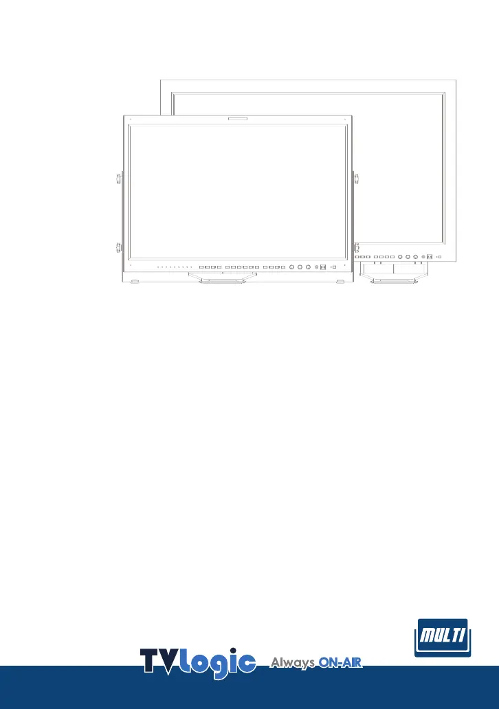
Multi Format Broadcast
LCD Monitor
Operation Manual_v2.6
LVM-245W
LVM-327W
LVM-328W
Multi Format LCD Monitor 3
1. Caution
2. Main Features
3. Controls & Functions
4. Menu Tree & Adjustment
5. Menu Operations
[1] PICTURE
[2] VIDEO
[3] COLOR
[4] DISPLAY
[5] GPI
[6] MARKER
[7] WAVEFORM
[8] AUDIO
[9] SYSTEM
6. Other Functions
7. DVI Support Resolution
8. Product Specications
9. Optional Accessories
04
06
07
12
15
15
16
17
19
20
25
26
29
30
32
35
36
39
FCC (Federal Communications Commission)
This equipment has been tested and f o
und
to comp
ly with
the limits for class A digital d evice, pursuant to part 15
of
the FCC Rules. These limits
are
designed
to p rovid
e rea
sonab
le protection against harm
fu
l interface wh
en t h
e
equip
ment is operated in a commercial e
nv
ironment.
This equ
ip
ment
generat
es,
use
s and ca
n radiat
e ra
dio frequency en
ergy and if not
inst
alled and used in
acc
ordanc
e wit
h the ins
tr
uction
m
anual, may cause ha
rmful inte
rf
erence t
o
rad
io commun
ications. Operation o f
this equipment in a residentia l t
o c orrect
the inter
ference a
t his
ow
n exp
ens
e
CAUTION: Change o
r modif icati
ons n
ot expr
essly approved by the m
an
ufac
tur
er responsible for
compliance
could void the users author
it
y t
o
ope
rate t
he equipmen
t.
Disposal of Ol
d Electrical & El
ect
ron
ic Equipmen
t
(Applicable in
t
he
Eu
rope
an
Union a n
d othe
r Europ
ean countrie
s with
sepa
rate c
ollection system
s)
This s
ymbol on the product
or on it
s packin
g in
di
cat
es that t
his produc
t sha
ll n
ot be treate
d as
hou
sehold
was
te. In
st
ead it sh
all be ha
nd
ed ov
er t
o the
a
pplicable collection point for th
e recyclin
g of
ele
ctr
ica
l a
nd
electr
onic equipment. By ens
uring this product is disposed
of correctly, you
wil l help
pre
ven
t pot
en
tial n
egative
conseq
uence f
or
the
environment and human
health, which cou
ld other
wise b e cau
sed by ina
ppropriate was
te
handling
of this product. Th
e recyclin
g of
mat
erials
w
ill help to conserve na
tural r
esources.
.....
.
........
...
.....
...
..
...........
.....
......
..
..
.......
...
.........
....
.....
...
...
..
..
...
...........
.....
......
..
..
..........
........
.....
...
..
..
...
..........
......
......
..
..
..........
........
.....
.
..
...
..........
......
......
..
..
..........
........
.....
..
...
...
..
..
...
...........
.....
......
..
..
..........
........
.....
........
...
.....
..
...
...........
.....
......
..
..
..........
........
.....
...
.
........
...
.....
...
..
...........
.....
......
..
..
.......
...
.........
....
..
.
........
...
.....
..
...
...........
.....
......
..
..
.......
...
........
.....
.
........
...
.....
..
...
...........
.....
......
..
..
.......
...
........
.....
......
.
........
...
.....
...
..
...........
.....
......
..
..
.......
...
.........
....
........
...
.....
..
...
...........
.....
......
..
..
..........
........
.....
....
...
...
..
..
...
...........
.....
......
..
..
..........
........
.....
..
.
........
...
.....
..
...
...........
.....
......
..
..
.......
...
........
.....
.
........
...
.....
..
...
...........
.....
......
..
..
.......
...
........
.....
....
...
...
..
..
...
...........
.....
......
..
..
..........
........
.....
.
..
..
...
..........
......
......
..
..
..........
........
.....
.
..
..
...
..........
......
......
..
..
..........
........
.....
...
..
..
...
..........
......
......
..
..
..........
........
.....
Multi Format LCD Monitor 5
• When mounting the product be sure to install
the product
according to the method recommended by
the manufacturer.
• Unplug the power cord from the AC outlet
before cleaning the product. Use a damp
cloth to clean the product. Do not use liquid
cleaners or aerosol cleaners.
• Unplug the power cord from the AC outlet if
you do not use the product for considerably
long time.
• Do not use the product near water, such as
bathtub, washbasin, kitchen sink and laundry
tub, swimming pool and in a wet basement.
• Keep the product away from direct rays of the
Sun-light.
• Do not place the product on an unstable cart,
stand, tripod or table. Placing the product on
an unstable base can cause the product to fall,
resulting in serious personal injuries as well as
damage to the product. Use only a cart, stand,
tripod, bracket or table recommended by the
manufacturer or sold with the product. When
mounting the product on a wall, be sure to
follow the manufacturer’s instruction. Use only
the mounting hardware recommended by the
manufacturer.
• When relocating the product placed on a cart,
it must be moved with the utmost care.
Sudden stops, excessive force and uneven
oor surface can cause the product to fall from
the cart.
• The vents and other openings in the cabinet
are designed for ventilation. Do not cover
or block these vents and openings since
insucient ventilation can cause overheating
and/or shorten the life of the product. Do not
place the product on a bed, sofa, rug or other
similar surface, since they can block ventilation
openings. This product is not designed for
built-in installation; do not place the product
in an enclosed place such as a bookcase or
rack, unless proper ventilation is provided or
the manufacturer’s instructions are followed.
• The LCD panel used in this product is made of
glass. Therefore, it can break when the product
is dropped or applied with impact. Be careful
not to be injured by broken glass pieces in
case the LCD panel breaks.
• Keep the product away from heat sources
such as radiators, heaters, stoves and other
heat generating products (including
ampliers).
<Main Switch>
To identify any terminal which is intended for
connection to an external conductor for
protection against electric shock in case
of a fault, or the terminal of a protective earth
(ground) electrode.
This mark indicates the
possibility of injury or
damage to property.
<Near the main terminal block><Beside critical components in circuit diagram>
means Power on when pressing
means Power o when pressing
6 Multi Format LCD Monitor
Compatible with varied SDI signals
- This product is compatible with various SDI
Signals : 480i, 576i, 720p, 1080i, 1080p,
1080psF (SDI A, B 2 channels are compatible).
Compatible with varied Analog signals
- This product is compatible with various
Analog signals - Composite, S-Video,
Component, RGB and etc.
All-in-one type system
- Slim and all-in-one type monitor as it
requires no additional accessories, for
optimized space utilization.
Wide Screen compatible
- Wide Screen (Native 16:9) for easier
monitoring conditions.
Remote Control Function
- This product can be remote controlled
simply with cable connection without
additional peripheral equipment attached to
the unit.
DVI/HDMI(HDCP) function built-in
- DVI(Analog), DVI(Digital) and HDMI(HDCP)
Inputs are available without the need of
extra accessories.
RS-422/UMD feature support
- This product supports protocols provided by
TVLogic or TSL.
RS-232 support
- Supports color-calibration through serial
communication.
Ethernet & USB support
- Supports Ethernet and USB connection for
program download and monitor control.
Dual Link support
- Supports Dual link YCbCr/RGB 4:4:4 and
YCbCr 4:2:2 formats.
3G support
- Supports 3G A/B formats.
Additional features
- Wide Viewing Angle, Loop Through out(SDI),
1300:1 contrast ratio, 500cd/m 2,
VESA
Mounting Standard and User Interface.
LVM-245W/327W/328W Monitors contain the following features:
Multi Format LCD Monitor 7
LVM-245W : FRONT
LVM-245W : REAR
STATUS
INDICATOR
ANALOG
SDI-A
SDI-B
PBP
F1
F2
F3
F4
POWER
POWER INDICATOR
ENTER
UP
DOWN
APERTURE
BRIGHT
CONTRAST
AUDIO OUT
USB
MENU
MARKER
SCAN
REMOTE
RS-422 IN
RS-422 OUT
RS-232
HDMI
AUDIO IN
DVI-I
CVBS1/Y/G/S-Y
CVBS2/Pb/B
CVBS3/Pr/R/S-C
SDI-IN A
SDI-OUT A
SDI-IN B
SDI-OUT B
LAN
AC IN
DC IN
8 Multi Format LCD Monitor
STATUS
INDICATOR
ANALOG
SDI-A
SDI-B
PBP
F1
F2
F3
F4
POWER
POWER INDICATOR
ENTER
UP
DOWN
APERTURE
BRIGHT
CONTRAST
AUDIO OUT
USB
MENU
MARKER
SCAN
RS-422 IN
RS-422 OUT
REMOTE
AC IN
SDI-B OUT
SDI-B IN
SDI-A OUT
SDI-A IN
RS-232
CVBS1/Y/G/S-Y
CVBS2/Pb/B
CVBS3/Pr/R/S-C
DVI-I
HDMI
AUDIO IN
LAN
LVM-327W/328W : FRONT
LVM-327W/328W : REAR
Multi Format LCD Monitor 13
[5] MENU TREE
PICTURE
BRIGHT
CONTRAST
CHROMA
PHASE
APERTURE
NTSC SETUP
VGA H POSITION
VGA V POSITION
FOCUS ASSIST LEVEL
FOCUS ASSIST COLOR
USER ASPECT HORIZONTAL
USER ASPECT VERTICAL
NOISE REDUCTION
VIDEO
DITHERING
FILTER
FAST MODE
FORCE psf
FILM MODE DETECTION
SDI FORMAT
SDI SAMPLING
3G FORMAT
OUTPUT MODE SELECT
COLOR
COLOR TEMP
GAIN RED
GAIN GREEN
GAIN BLUE
BIAS RED
BIAS GREEN
BIAS BLUE
BACK LIGHT
COLOR SPACE
GAMMA CURVE
DISPLAY
HD DISPLAY MODE
TIME CODE ENABLE
ORBITER CIRCUIT
CLOSED CAPTION
608 CAPTION SELECT
708 SERVICE SELECT
TELETEXT PAGE
SCREEN SELECT
BORDER COLOR
BODER THICKNESS
GPI
GPI 1~GPI 8
MONITOR ID
UMD DISPLAY
UMD CHARACTER
D-UMD TALLY TYPE
TALLY 1 COLOR / B0:0 B1:0
TALLY 2 COLOR / B0:0 B1:0
TALLY 3 COLOR / B0:0 B1:0
TALLY 4 COLOR / B0:0 B1:0
PASSWORD
IP ADRESS
SUBNET MASK
GATEWAY
PORT NO
REMOTE CONTROL
UMD CHRACTER COLOR
UMD BG.TRANS
Multi Format LCD Monitor 17
[3] COLOR
COLOR TEMP
- Used to control the Color Temperature
and allow instant access to preset color
temperature settings.
- Available values are 3200K, 5000K, 5600K,
6500K, 9300K and CUSTOM 1/2/3.
- In CUSTOM1/2/3 modes, user can dene
custom RGB GAIN and BIAS values.
- Backlight value is adjustable for each color
temperature.
GAIN RED
- Used to control the RED color.
- The value is selectable between Min(-256)
and MAX(255).
- Adjusts red color of bright sections.
- Only available in CUSTOM 1/2/3 modes.
GAIN GREEN
- Used to control the GREEN color.
- The value is selectable between Min(-256)
and MAX(255).
- Adjusts green color of bright sections.
- Only available in CUSTOM 1/2/3 modes.
GAIN BLUE
- Used to control the BLUE color.
- The value is selectable between Min(-256)
and MAX(255).
- Adjusts blue color of bright section.
- Only available in CUSTOM 1/2/3 modes.
BIAS RED
- Used to adjust the black level to control RED
color.
- The value is selectable between Min(-100)
and MAX(100).
- Adjusts RED color of dark sections.
- Only available in CUSTOM 1/2/3 modes.
BIAS GREEN
- Used to adjust the black level to control
GREEN color.
- The value is selectable between Min(-100)
and MAX(100).
- Adjusts green color of dark sections.
- Only available in CUSTOM 1/2/3 modes.
BIAS BLUE
- Used to adjust the black level to control BLUE
color.
- The value is selectable between Min(-100)
and MAX(100).
- Adjusts blue color of dark sections.
- Only available in CUSTOM 1/2/3 modes.
COLOR COPY
- Used to copy the R/G/B Gain value of pre-
stored color temperature settings.
- In CUSTOM mode, nd and select the color
temperature to be used by using the [UP]/
[DOWN] buttons and press the [ENTER]
button to copy and apply the Gain Value to
GAIN RED, GAIN GREEN, GAIN BLUE.
- Only available in CUSTOM 1/2/3 modes.
PAGE I >> PAGE II
COLOR TEMP
GAIN RED
GAIN GREEN
GAIN BLUE
BIAS RED
BIAS GREEN
BIAS BLUE
COLOR COPY
6500K
0
0
0
0
0
0
6500K
LVM-327WSDI A 1080/60i
18 Multi Format LCD Monitor
BACK LIGHT
- Used to control the LCD Panel’s brightness.
- Available values are from 0 to 100.
COLOR SPACE
- Used to select the Color Space.
- Available modes are NATIVE COLOR, REC-
709(sRGB), LUT SMPTE-C and LUT EBU.
GAMMA CURVE
- Used to change the Gamma Curve from 1.0
to 3.0.
- Available values are from 1.0 to 3.0.
[3] COLOR
PAGE II >> PAGE I
BACKLIGHT
COLOR SPACE
GAMMA CURVE
50
NATIVE COLOR
2.20
LVM-327WSDI A 1080/60i
Multi Format LCD Monitor 21
MONITOR ID
- Used to set the ID of each monitor for the
TVLogic control protocol or DYNAMIC UMD
using RS-422 communication.
- Available values are between 0,1,2 ~ 124.
- Right screen in PBP mode is automatically set
to +1 of the monitor ID.
UMD DISPLAY (Under Monitor Display)
- Used to set input source ID mode.
- Available modes are OFF, UMD, ANC, D-UMD
(S-8C), D-UMD(S-16C) and D-UMD(D-8C).
- If the UMD menu is selected, characters or
tally data in the black bar displays on the
bottom of the screen. The vertical aspect
ratio of the image changes on the screen as
the bar appears at the bottom of screen.
- In the USER ASPECT mode, the UMD bar
displays semi-transparently and the screen
keeps its USER ASPECT ratio.
* UMD : Displays user customized 8 characters
on screen.
* ANC : Displays characters embedded in SDI
signal.
* D-UMD(S-8C) : Displays incoming data of 8
characters and tally signal from TSL protocol
(V3.1).
* D-UMD(S-16C) : Displays incoming data of 16
characters and tally signal from TSL protocol
(V3.1).
* D-UMD(D-8C) : Displays incoming data of
two pairs of 8 character strings and tally
signals from TSL protocol (V3.1).
- In PBP mode, even if D-UMD(S16C), D-UMD
(D-8C) and D-UMD(S-8C) are selected, only
D-UMD (S-8C) activates.
- In PBP mode, each D-UMD(S-8C) for left
screen and right screen are activated.
Adjustments for each setting are available.
UMD CHARACTER
- Used to customize the characters for UMD.
- Alphabets, numbers and special symbols are
available. (Max. 8 characters)
D-UMD TALLY TYPE
- Tally type conguration setting in D-UMD(D-
8C), UMD Display.
- Conguration values are DEFAULT, USER
COLOR, CHARACTER, BG .COLOR,
USER TALLY, USER CHAR and USER BG.
* DEFAULT : Existing TV Logic operating
system (VRT)
* USER COLOR : User conguration settings on
each TALLY color type.
- TALLY1 COLOR ~ TALLY4 COLOR are activated
when USER COLOR is selected.
- CHARACTER : Tally displays with the
character color. Activates the same as
Default model.
- BG. COLOR : Tally is displayed as the
background of character. Activate the same as
Default mode.
- USER TALLY : The bit0 & bit 1 of TSL Protocol
Control Byte receives the input signal and
displays Tally by user’s set (OFF, WHITE, RED,
GREEN, BLUE, YELLOW CYAN, MAGENTA)
- USER CHAR : This function activates in
the same way as USER TALLY and TALLY is
displayed by the character color.
- USER BG. : This function activates in the same
way as USER TALLY and Tally is displayed in
the background of the character.
TALLY1 COLOR ~ TALLY4 COLOR
- This item sets the color of each TALLY1,
TALLY2, TALLY3 and TALLY4 .
- Available color settings are Red, Green and
Yellow.
B0:0 B1:0 ~ B0:1 B0:1
- The Byte0, Byte1 of TSL Protocol Control Byte
sets the color of the input conditions.
- Available colors are OFF, WHITE, RED, GREEN,
BLUE, YELLOW, CYAN and MAGENTA.
LVM-327WSDI A
[5] GPI
PAGE II >> PAGE III
MONITOR ID
UMD DISPLAY
UMD CHARACTER
D-UMD TALLY TYPE
TALLY 1 COLOR
TALLY 2 COLOR
TALLY 3 COLOR
TALLY 4 COLOR
O
OFF
CHANNEL L1
DEFAULT
OFF
OFF
OFF
OFF
1080/60i
22 Multi Format LCD Monitor
[5] GPI
<Dynamic UMD Protocol (TSL V3.1)>
* Transmission (18 Byte) (PC or Device -> Monitor)
* [HEADER] : Display address (0~126) + 80 hex.
* [CONTROL BYTE]
bit 0 : Tally 1 (1=on, 0=o)
bit 1 : Tally 2 (1=on, 0=o)
bit 2 : Tally 3 (1=on, 0=o)
bit 3 : Tally 4 (1=on, 0=o)
bit 4 : bright data (Not used)
bit 5 : bright data (Not used)
bit 6 : reserved (Not used)
bit 7 : cleared to 0 (Not used)
* [DISPLAY DATA] : 16 displayable ASCII characters.
HEADER
(1 BYTE)
CONTROL
BYTE(1 BYTE)
DISPLAY DATA
(16 BYTE)
Tally1 CHANNEL1 Tally2 Tally3 CHANNEL1 Tally4
26 Multi Format LCD Monitor
USER MARKER H1
- Used to control the position of the rst user
dened horizontal marker line.
- Marker option USER needs to be selected.
USER MARKER H2
- Used to control the position of the second
user dened horizontal marker line.
- Marker option USER needs to be selected.
USER MARKER V1
- Used to control the position of the rst user
dened vertical marker line.
- Marker option USER needs to be selected.
USER MARKER V2
- Used to control the position of the second
user dened vertical marker line.
- Marker option USER needs to be selected.
WAVEFORM/VECTOR
- This function sets the WAVEFORM and
VECTORSCOPE.
- This feature is available in SDI, COMPOSITE
1/2/3, S-VIDEO and COMPONENT modes.
- Activates in the order :
* Normal mode : OFF-> WAVEFORM->
VECTOR-> YCbCr-> RGB-> WAVEFORM +
VECTOR-> WIDE-Y.
* PBP mode : OFF-> WAVEFORM-> VECTOR->
->WIDE-Y.
- Displays on the bottom right of the screen
and moves above the UMD, if UMD feature is
selected.
* WAVEFORM : Displays the shape and form of
luminance level of a signal.
* VECTOR : Displays the color components B-Y
and R-Y of the input signals on the XY axis.
HD and SD inputs are classied into two
kinds, depending on the input. 100% and
75% scales indicated on a display.
* YCbCr : Displays each waveform for elements
of the luminance and Cb/Cr of the input s
ignal.
* R/G/B : Displays each waveform for elements
of the green, red and blue of the input signal.
* WAVEFORM + VECTOR : Displays waveform
and vector scope simultaneously.
* WIDE-Y : Stretches the waveform to t the
width of the screen.
- When the input signal format is RGB 444,
only the RGB mode activates.
LVM-327WSDI A
[6] MARKER [7] WAVEFORM
PAGE II >> PAGE I
USER MARKER H1
USER MARKER H2
USER MARKER V1
USER MARKER V1
MIN
MIN
MIN
MIN
PAGE I >> PAGE II
WAVEFORM/VECTOR
WAVEFORM INTENSITY
WAVEFORM TRANS
WAVEFORM SIZE
LINE WAVEFORM ENABLE
LINE POSITION SELECT
LINE POSITION DRAW
OFF
OFF
OPAQUE
NORMAL
OFF
0
OFF
LVM-327W1080/60i 1080/60i
Multi Format LCD Monitor 27
[7] WAVEFORM
PAGE I >> PAGE II
WAVEFORM/VECTOR
WAVEFORM INTENSITY
WAVEFORM TRANS
VECTOR GAIN X 4
LINE WAVEFORM ENABLE
LINE POSITION SELECT
LINE POSITION DRAW
WAVEFORM COLOR
OFF
OFF
OPAQUE
OFF
OFF
0
OFF
WHITE
WAVEFORM INTENSITY
- Used to control the brightness of the
WAVEFORM/VECTOR display.
- Available values are between 0 ~ 30. The
higher the number the brighter the
Waveform will be.
WAVEFORM TRANS
- Used to control the transparency level of the
WAVEFORM/VECTOR.
- Available modes are OPAQUE and TRANS.
- If the main OSD overlaps with the
WAVEFORM/VECTOR when the option is set
to OPQGUE, it will automatically display it
as transparent and change back to OPAQUE
when the main OSD disappears.
VECTOR GAIN X 4
- This item magnies the precision of
VECTORSCOPE four times size based on the
center of the vectorscope.
LINE WAVEFORM ENABLE
- This item is utilized to display the entire data
or one line data on the waveform.
LINE POSITION SELECT
- In the WAVEFORM/VECTOR, use the [Up]/
[Down] button to select User’s desired line.
LINE POSITION DRAW
- ON/OFF the line indication for line select
feature.
- Activates only when the LINE SELECT ENABLE
feature is enabled.
- When this item is set to OFF, the Line
Waveform still displays if LINE WAVEFORM is
enabled.
WAVEFORM COLOR
- This item selects the color of WAVOFORM/
VECTOR.
- Available options are WHITE and GREEN.
<WAVEFORM>
<WAVEFORM + VECTOR>
<VECTOR> <YCbCr/RGB>
<WIDE-Y>
WAVE
FORM
WAVE
FORM
VEC
TOR
VEC
TOR Y/R
WAVEFORM
Cb/G Cr/B Position changes if the value
changes in LINE SELECT option
and the waveform of the selected
position displays.
WAVEFORM/VECTOR : WAVEFORM
LINE POSITION SELECT : ON
LINE POSITION DRAW : ON
WAVE
FORM
LVM-327W 1080/60i
28 Multi Format LCD Monitor
[7] WAVEFORM
RANGE ERROR
- Used to display the values of Y MAX, Y MIN, C
MAX, C MIN, Y PICTURE BLINK and C PICTURE
BLINK on the screen.
- Selected values in Y MAX, Y MIN, C MAX, C
MIN are indicated in WAVEFORM/VECTOR or
Y/Cb/Cr.
- If Y PICTURE BLINK or C PICTURE BLINK is
enabled, the section of image that exceeds
the selected values of Y MAX, Y MIN, C MAX
and C MIN blinks.
* In th case of RGB input, Range Error is not
supported
Y MAX
- Used to set the maximum luminance level.
- Available values are between 1 ~ 1020.
- Exceeded selection displays on the top
portion of the Waveform or display.
Y MIN
- Used to set the minimum luminance level.
- Available values are between 1~ 1020.
- Exceeded selection displays on the top
portion of the Waveform or display.
C MAX
- Used to set the maximum chroma level.
- Available values are between 1 ~ 1020.
- Exceeded selection displays on the top
portion of the Waveform or display.
C MIN
- Used to set the minimum chroma level.
- Available values are between 1 ~ 1020.
- Exceeded selection displays on the top
portion of the Waveform or display.
PAGE II >> PAGE I
RANGE EROR
Y MAX
Y MIN
C MAX
C MIN
Y PICTURE BLINK
C PICTURE BLINK
OFF
MAX
MIN
MAX
MIN
OFF
OFF
Y PICTURE BLINK
- Used to set selections of image that exceeds
Y MAX and Y MIN to blink.
C PICTURE BLINK
- Used to set selections of image that exceeds
C MAX and C MIN to blink.
LVM-327W 1080/60i
Multi Format LCD Monitor 31
[9] SYSTEM
PAGE III >> PAGE I
BOARD VERSION 0001 01 0.01 7
MAIN PBP1 PBP2
BRIG : 0 0 0
CONT : 0 0 0
COLOR : 6500K 6500K 6500K
SCAN : ZERO OVER OVER
ALM : OFF OFF OFF
KEY FUNCTION 4
- User can select the function for [F4] button.
- Selectable Items : ASPECT, H/V DELAY,
FREEZE, WAVEFORM SEL., W/F ON/OFF,
TIMECODE, CC SEL, ALM SEL., OUTPUT
MODE, DITHERING, FILTER,FORCE Psf, UMD,
COLOR TEMP, BLUE ONLY, PAGE 801, PAGE
888 and PAGE 889.
KEY LOCK
- This item locks all buttons and knobs on the
front panel except power, input select, and
menu buttons.
INFOMATION
- Displays board version and current status
information.
GPU VERSION
FPGA VERSION
MCU VERSION
KEYPAD VERSION
PAGE II >> PAGE III
KEY LED
KEY FUNCTION 1
KEY FUNCTION 2
KEY FUNCTION 3
KEY FUNCTION 4
KEY LOCK
ON
ASPECT
H/V DELAY
FREEZE
TIMECODE
DISABLE
LVM-327W LVM-327WSDI A SDI A
KEY LED
- This item controls KEY LED ON/OFF.
- If the button with LED is pressed with the
KEY LED O, LED comes on but goes o after
5 seconds.
KEY FUNCTION 1
- User can select the function for [F1] button.
- Selectable Items : ASPECT, H/V DELAY,
FREEZE, WAVEFORM SEL., W/F ON/OFF,
TIMECODE, CC SEL, ALM SEL., OUTPUT
MODE, DITHERING, FILTER,FORCE Psf, UMD,
COLOR TEMP, BLUE ONLY, PAGE 801, PAGE
888 and PAGE 889.
* [F1] button is used to select a SCREEN SEL in
PBP mode.
KEY FUNCTION 2
- User can select the function for [F2] button.
- Selectable Items : ASPECT, H/V DELAY,
FREEZE, WAVEFORM SEL., W/F ON/OFF,
TIMECODE, CC SEL, ALM SEL., OUTPUT
MODE, DITHERING, FILTER,FORCE Psf, UMD,
COLOR TEMP, BLUE ONLY, PAGE 801, PAGE
888 and PAGE 889.
KEY FUNCTION 3
- User can select the function for [F3] button.
- Selectable Items : ASPECT, H/V DELAY,
FREEZE, WAVEFORM SEL., W/F ON/OFF,
TIMECODE, CC SEL, ALM SEL., OUTPUT
MODE, DITHERING, FILTER,FORCE Psf, UMD,
COLOR TEMP, BLUE ONLY, PAGE 801, PAGE
888 and PAGE 889.
1080/60i 1080/60i
34 Multi Format LCD Monitor
- OVER SCAN : Zooms in/out of the image
to 96% of its original size without
changing the aspect ratio.
- ZERO SCAN : Zooms in/out of the image
without changing the aspect ratio.
- UNDER SCAN : Zooms in/out of the image
without changing the aspect ratio. Also,
displays the data at the top of the
horizontal blanking block.
- 2:1 SCAN : Magnies the original image
twice the size. This feature is available
only when the size of the original image is
½ size or smaller than the screen size.
- 1:1 SCAN : 1:1 pixel mapping of original
image. This feature is available only
when the size of the original image is
bigger than the screen size. Press the
[ENTER] button to rotate the position.
MID LEFT -> TOP LEFT -> TOP MID -> TOP
RIGHT -> MID RIGHT -> BOT RIGHT -> BOT
MID -> BOT LEFT
- FIT WIDTH : In SD mode, zooms in to t
width of the original image to the width
of the screen without changing the a
spect ratio.
- USER ASPECT : Displays in user aspect
ratio of HORIZONTAL and VERTICAL value
that is selected under USER ASPECT item
in the [PICTURE] MENU.
- 3 X ZO O M : This feature is only available
under PBP 16:9 mode and displays the
image with 2 x zoom in.
When “3 X ZOOM” message window
appears, press the [ENTER] button to
activate vertical position control of image.
Use the [UP]/[DOWN] button to adjust the
vertical position of image. Press the
[ENTER] button again to activate
horizontal position control of image.
Use the [UP]/[DOWN] button to adjust the
horizontal position of image.
[4] SCAN
<Position change in 1:1 SCAN>
<MID CENTER>
<TOP MID>
<BOT RIGHT>
<MID LEFT>
<TOP RIGHT>
<BOT MID>
<TOP LEFT>
<MID RIGHT>
<BOT LEFT>

Produktspecifikationer

Varumärke: TVLogic
Kategori: högtalare
Modell: LVM-328W

Behöver du hjälp?

Om du behöver hjälp med TVLogic LVM-328W ställ en fråga nedan och andra användare kommer att svara dig


högtalare TVLogic Manualer

högtalare Manualer

Nyaste högtalare Manualer