EBERLE ITR 3 528 35 Bruksanvisning
Läs gratis den bruksanvisning för EBERLE ITR 3 528 35 (2 sidor) i kategorin Termostat. Guiden har ansetts hjälpsam av 46 personer och har ett genomsnittsbetyg på 4.4 stjärnor baserat på 4 recensioner. Har du en fråga om EBERLE ITR 3 528 35 eller vill du ställa frågor till andra användare av produkten? Ställ en fråga
Sida 1/2
Montage- und Bedienungsanleitung
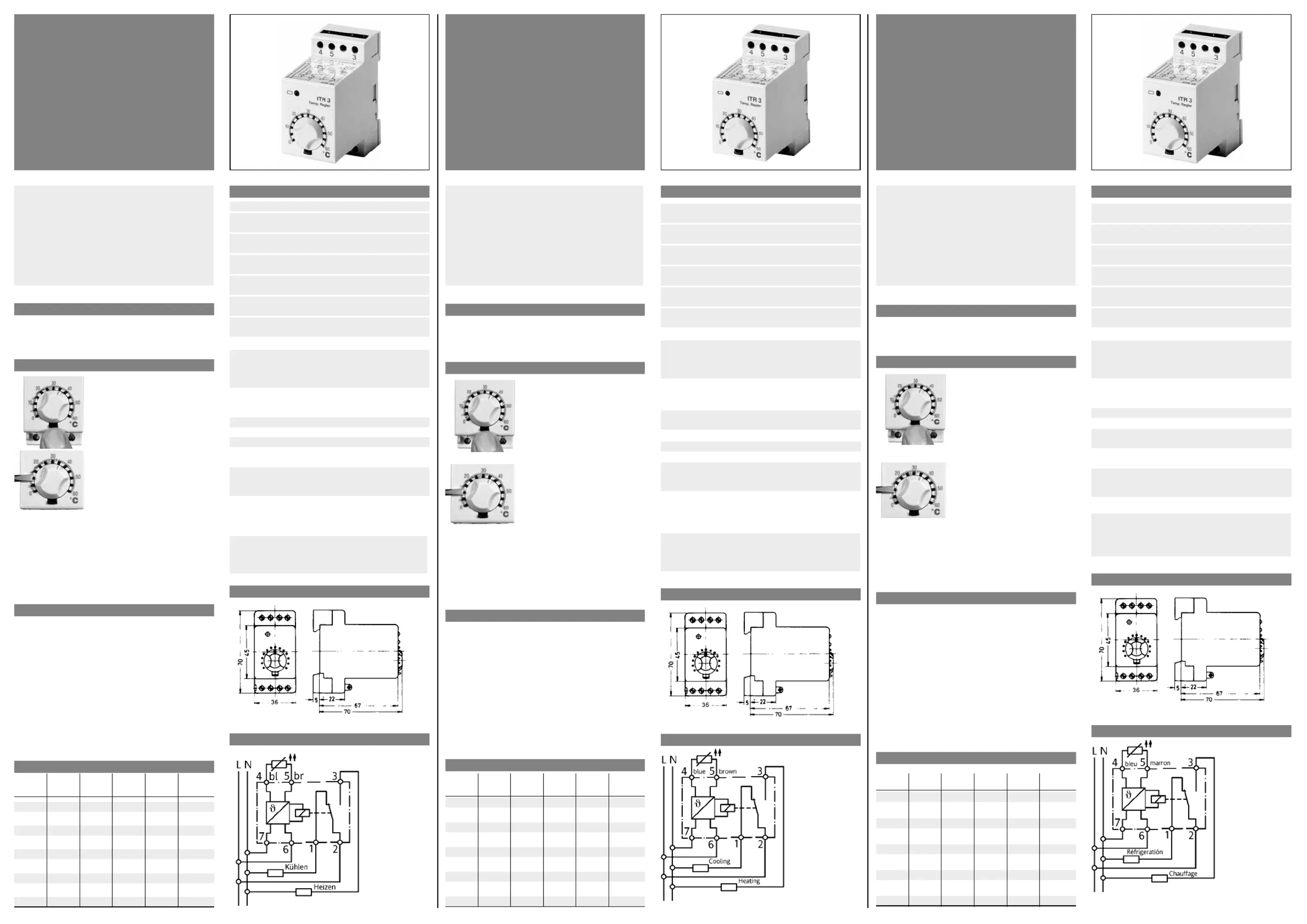
Temperaturregler ITR 3
528 35
U 468 931 001311-6
Montage
Der Regler wird auf 35 mm Normschiene aufgeschnappt.Der
elektrische Anschluss erfolgt entsprechend dem aufgedruck-
ten Schaltbild.
Funktionen
Die gewünschte Temperatur wird mit-
tels Drehknopf an der Frontseite des
Reglers eingestellt.
Diese Einstellung kann mittels der
Taste unterhalb des Einstellknopfes
arretiert werden.
Ebenso ist eine Bereichseinengung
möglich. Diese wird in 5°C-Teilen
durch die Stifte an der Temperatur-
skala vorgenommen.
Bitte beachten Sie:Arretierung und Bereichseinengung
dienen als Schutz gegen unbeabsichtigtes Verstellen.
Betätigen Sie den Einstellknopf niemals gewaltsam. Lässt sich
dieser nicht oder nur schwer betätigen, überprüfen Sie, ob
eine der beiden Arretierungsfunktionen betätigt ist.
Bis die eingestellte Temperatur erreicht wird, sind die
Kontakte 2 und 3 geschlossen. Die grüne LED leuchtet.
Fernfühler
Bei Einsatz des Standardfühlers in Flüssigmedien ist die
Verwendung eines Schutzrohres erforderlich.
Ein Rohranlegefühler soll möglichst großflächig an dem zu
regelnden Rohr anliegen.
Bei Einsatz des Luftfühlers ist darauf zu achten, dass die
Schlitzöffnungen in der Luftströmung liegen.
Das Fühlerkabel kann bei einem Querschnitt von 1,5mm
2
bis
auf 50m verlängert werden, ohne die Genauigkeit des
Reglers zu beeinträchtigen. Bei Verlegen des Fühlerkabels in
Kabelkanälen oder in der Nähe von Starkstromleitungen
muss eine abgeschirmte Leitung verwendet werden. Der
Schirm ist an Klemme 4 anzuschließen.
Fühlerkenndaten
RRR
(°C)()(°C)()(°C)(ΩΩΩ)
–555002510001101774
–505253010391201882
–405774011181251937
–306325012021301993
–206916012881402107
–107547013791502225
08208014721602346
108899015691702471
2096210016701752535
Achtung!
Dieses Gerät darf nur durch einen Fachmann gemäß
dem Schaltbild am Gehäuse installiert werden. Dabei
sind die bestehenden Sicherheitsvorschriften zu beach-
ten.
Dieser zum Schalttafeleinbau bestimmte elektronische
Regler ist geeignet zur Montage in trockenen und
geschlossenen Räumen mit üblicher Umgebung. Der
Regler arbeitet nach der Wirkungsweise 1 C.
Technische Daten
Netzversorgung
NennspannungAC 220/230 V
Toleranzbereich187 ... 242 V
NennspannungAC 240 V
Toleranzbereich204 ... 264 V
NennspannungAC 110/115 V
Toleranzbereich93 ... 127 V
NennspannungAC 24 V
Toleranzbereich20,4 ... 26,4 V
Frequenz50/60 Hz
Frequenzbereich48 ... 62 Hz
NennspannungDC 24 V
Toleranzbereich21,6 ... 26,4 V
SchaltvermögenAC 250 V, 10 (4) A
Temperaturbereiche
Sollwertangabe–40 … 20°C / 0 … 60°C
20 … 80°C / 40 … 100°C
100 … 160°C
Umgebungstemperatur
Betrieb–10 … 50°C
Lagerung–40 … 70°C
Stat. Hysterese1 K
Kontaktart1 Wechsler potentialfrei*
Bemessungsstoßspannung 2,5 KV
Temperatur für die
Kugeldruckprüfung 75°C
Spannung und Strom für230V, 10A
Zwecke der EMV-
Störaussendungsprüfungen
*) Achtung
Die potentialfreien Kontakte dieses netzbetriebenen Gerätes ge-
währleisten nicht eine mögliche Forderung nach Schutzklein-
spannung (sichere Trennung).
Maßskizze
Schaltbild
HINWEIS:
Bei der 24 V-Version muss die Versorgung aus einem
Schutzkleinspannungsnetz erfolgen.
Notice de
montage et d’utilisation
Thermostat ITR 3
528 35
U 468 931 001311-6
Montage
Sur rail DIN de 35 mm. Le branchement doit être fait selon le
schéma qui se trouve sur l’appereil.
Fonction
La température souhaitée est affichée
par le bouton en facade. Ce réglage
peut être bloqué par la touche située
sous le bouton.
Il est également possible de choisir
une plage de réglage de température
par l’intermédiaire de picots, par
intervalles de 5°C.
Ces deux possibilités sont prévues
pour éviter tout dérèglement accidentel de la température
progammée.
Ne pas forcer le bouton de réglage; si celui-ci offre une rési-
stance, contrôler si aucune des sécurités n’est mise.
Sonde ą distance
La sonde standard ne peut être utilisée dans un milieu liqui-
de qu’à l’intérieur d’un doigt de gant.
La sonde applique doit avoir une surface maximale en
contact avec le tuyan à surveiller.
La sonde pour veine d’air doit être placée de manière à ce
que ses ouvertures soient dans le sens du courant d’air.
Il est possible de rallonger jusqu’à 50 m le câble, en utilisant
un fil de section 1,5 mm
2
sans altérer la précision.
Si le câble est posé dans un chemin de câble ou à proximité
de câbles d’alimentation, il faut employer du câble blindé.
Raccorder le blindage à la borne 4.
Caractéristiques des sondes
RRR
(°C)()(°C)(ΩΩ)(°C)(Ω)
–555002510001101774
–505253010391201882
–405774011181251937
–306325012021301993
–206916012881402107
–107547013791502225
08208014721602346
108899015691702471
2096210016701752535
ATTENTION!
Cet appareil ne peut être monté que par un spécialiste
conformément au schéma de raccordement sur le
boîtier. Respecter les consignes de sécurité en vigueur.
Ce régulateur électronique à montage en tableau est
destiné à être installé dans des locaux secs et fermés
soumis à des conditions usuelles. Ce régulateur fonc-
tionne en mode 1 C.
Caractéristiques techniques
Tension d’alimentationAC 220/230 V
Tolèrance187 ... 242 V
Tension d’alimentationAC 240 V
Tolèrance204 ... 264 V
Tension d’alimentationAC 110/115 V
Tolèrance93 ... 127 V
Tension d’alimentationAC 24 V
Tolèrance20,4 ... 26,4 V
Frequence50/60 Hz
Tolèrance48 ... 62 Hz
Tension d’alimentationDC 24 V
Tolèrance21,6 ... 26,4 V
Pouvoir de coupureAC 250 V, 10 (4) A
Plages de temperature
Affichage de la–40 … 20°C / 0 … 60°C
valeur de sonsigne20 … 80°C / 40 … 100°C
100 … 160°C
Température
Ambiante–10 … 50°C
Stockage–40 … 70°C
Hystèrèsis staique1 K
Contact1 inverseur*
Surtension transitoire 2,5 KV
dimensionnée
Température d’essai 75°C
Brinell
Tension et courant de 230 V, 10 A
contrôle decompatibilité
électromagnétique
Plan cote
Schémas de raccordement électrique
REMARQUE:
La version 24 V doit être alimentée par un reseau basse-
tension de sécurité.
Mounting and operating instructions
Thermostat ITR 3
528 35
U 468 931 001311-6
Mounting
The thermostat is designed for mounting on to 35 mm rail
according to EN 50 022. Electrical connections are according
to the wiring diagram.
Functions
The desired temperature is set via the
knob on the front of the controller.
The setting can be locked with the
button located below the setting
knob. A 5°C limit is possible with the
use of tappets on the temperature
scale.
Please note: Locking and range limits are provided to pro-
tect against incorrect settings. Never turn the setting knob
using force. If it cannot be turned easily, check wheter or not
the control knob is locked.
Contacts 2 and 3 are made until the set temperature is rea-
ched. The green LED lights up.
Remote sensor
When using the standard sensor in liquids a pocket must be
used. The sensor should be in contact with as large a surfa-
ce area as possible.
When using the air sensor it is important that the air ducts
are sited correctly for air flow.
The sensor cable, with a diameter of 1.5 mm
2
, can be exten-
ded up to 50 m without adverse effect on the accuracy of
the controller. When the sensor cable is laid in cable ducts
or near high current cables, it may be necessary to use scre-
ened cable. The screen shall be connected to terminal 4.
Sensor data
RRR
(°C)()(°C)()(°C)(ΩΩΩ)
–555002510001101774
–505253010391201882
–405774011181251937
–306325012021301993
–206916012881402107
–107547013791502225
08208014721602346
108899015691702471
2096210016701752535
Note!
This device must be installed by an expert according to
the circuit diagram on the housing. The existing safety
regulations must be complied with. This electronic regu-
lator is designed to be installed in the control panel and
is suitable for installation in dry and closed rooms with
standard atmospheric conditions. The controller works
according to operation method 1C.
Technical Data
Operating voltageAC 220/230 V
Tolerance187 ... 242 V
Operating voltageAC 240 V
Tolerance204 ... 264 V
Operating voltageAC 110/115 V
Tolerance93 ... 127 V
Operating voltageAC 24 V
Tolerance20.4 ... 26.4 V
Frequence50/60 Hz
Tolerance48 ... 62 Hz
Operating voltageDC 24 V
Tolerance21.6 ... 26.4 V
Switching CapacityAC 250 V, 10 (4) A
Temperature ranges
Nominal value–40 … 20°C / 0 … 60°C
indication20 … 80°C / 40 … 100°C
100 … 160°C
Ambient temperature
Operating–10 … 50°C
Storage–40 … 70°C
Static switching
differential1 K
Contact1 change over
Rated impulse voltage2.5 KV
Brinell test temperature75°C
Voltage and current for 230 V, 10 A
EMC emitted
interference testing
NOTE:
The volt-free contact of this mains operated unit does not ensu-
re the requirement for the use of safety extra-low voltage (SELV).
Dimension drawing
Wiring diagram
NOTE:
24 V Version. Supply has to be made via protected small
voltage mains.
Produktspecifikationer
| Varumärke: | EBERLE |
| Kategori: | Termostat |
| Modell: | ITR 3 528 35 |
Behöver du hjälp?
Om du behöver hjälp med EBERLE ITR 3 528 35 ställ en fråga nedan och andra användare kommer att svara dig
Termostat EBERLE Manualer

24 Augusti 2025
24 Augusti 2025
24 Augusti 2025
24 Augusti 2025
24 Augusti 2025
24 Augusti 2025
23 Augusti 2025
23 Augusti 2025
23 Augusti 2025
23 Augusti 2025
Termostat Manualer
Nyaste Termostat Manualer
2 April 2026
1 April 2026
31 Mars 2026
30 Mars 2026
19 Mars 2026
16 Mars 2026
14 Mars 2026
25 Februari 2026
13 Oktober 2025
12 Oktober 2025