ESYLUX SLE EL LED 3h/8h 23m IR SC/C SM Bruksanvisning
Läs gratis den bruksanvisning för ESYLUX SLE EL LED 3h/8h 23m IR SC/C SM (6 sidor) i kategorin Lampa. Guiden har ansetts hjälpsam av 9 personer och har ett genomsnittsbetyg på 4.3 stjärnor baserat på 5 recensioner. Har du en fråga om ESYLUX SLE EL LED 3h/8h 23m IR SC/C SM eller vill du ställa frågor till andra användare av produkten? Ställ en fråga
Sida 1/6
KURZANLEITUNG
GEFAHR!
Lebensgefahr durch elektrischen Schlag!
• Die Install
ation darf nur von Elektroinstallateuren oder
Elektrofachkräften unter Berücksichtigung der landesspezifischen
Vorschriften erfolgen
• Vor Montage / Demontage die Leitung bzw. die Anschlüsse von der
Netzspannung freischalten
• Die Installation muss allen geltenden örtlichen Vorschriften entsprechen.
• Halten Sie alle Verpackungsmaterialien von Kindern und Haustieren
fern – diese Materialien stellen eine potenzielle Gefahrenquelle dar,
z. B. Ersticken
• Entnehmen und
überprüfen Sie alle Komponenten vor Gebrauch
1 Bestimmu
ngsgem
äße Verwendung
Die Notleuchte ist für die Anwendung im Innenbereich konzipiert
und übernimmt bei Ausfall der Stromversorgung im Stromkreis die
Kennzeichnung der Rettungswege. Das Produkt ist für die Nutzung in
privaten Haushalten, sowie für gewerbliche Zwecke vorgesehen.
Die Lichtquelle der Notleuchte ist nicht ersetzbar. Wenn die Lichtquelle
ihr Lebensdauerende erreicht hat, ist die gesamte Notleuchte zu ersetzen.
Ein Austausch des Akkus oder der gesamten Notleuchte ist erforderlich,
wenn diese nicht mehr die Anforderungen an die Bemessungsbetriebsdauer
erfüllen. Verwenden Sie mit dem Produkt nur Akkus vom Typ EN10077784
SLE/ SLF BATTERY LiFePO4 1500mAh. Beim Herausnehmen des Akkus
muss das Produkt vom Stromnetz getrennt werden.
Montageart / -ort
Aufbau / Wand, Decke
Lieferumfang
1x Notleuc
hte, inklusive Leuchtmittel und wiederaufladbarem Akku
1x Piktogramm-Satz bestehend aus Piktogramm-Folien:
… SM (1x links, 1x rechts, 1x oben, 2x unten, 1x weiß)
… WM (1x links, 1x rechts, 1x oben, 1x unten)
1x Kurzanleit
ung
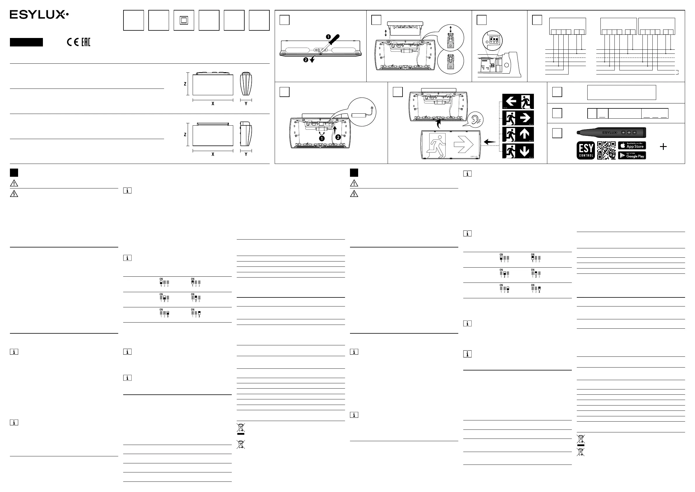
2 Montage
1. Drücken Sie die dr
ei Einkerbungen an der Unterseite des Produkts ein,
um die transparente Frontscheibe vom Produkt zu lösen (1.1). Verwenden
Sie einen Schraubendreher
, falls nötig.
Entfernen Si
e die Abdeckung im Falle einer Beschädigung nicht
mit Gewalt. Wenn die Abdeckung beschädigt ist, erfüllt das
Produkt nicht mehr die Schutz
klasse IP54.
2. Bewe
gen Sie die beiden Feststellschieber nach außen. Die Stifte sind
nun entriegelt (1.2). Drücken Sie die Stifte nach außen, um die Wand-/
Deckenhalterung vom Gehäuse zu lösen.
3. Befestigen Sie die Wand-/ Deckenhalterung mit 2Schrauben und
2Dübeln an der Wand/ Decke und führen Sie die Leitungen dabei in
Richtung der Anschlüsse.
4. Verbinden Sie die Leitungen mit den Anschlüssen und konfigurieren
Sie die DIP-Schalter (1.3).
5. Befestigen Sie das Gehäuse an der Wand-/ Deckenhalterung,
in dem Sie die Stifte durch die Stiftlöcher in das Gehäuse einführen
und die beiden Feststellschieber nach innen schieben (1.2).
6. Wählen Sie die gewünschte Piktogramm-Folie und legen Sie diese mit
der Abbildung nach
unten in die transparente Frontscheibe ein (1.5).
Die
Ränder der Piktogramm-Folie müssen sich unter den Clips am
Rand der transparenten Frontscheibe befinden. Die Clips haben
unterschiedliche Abstände. Bringen Sie die Piktogramm-Folie in
der richtig
en Position an.
7. Fügen Sie die Clips der transparenten Frontscheibe in die Steck-
schächte an der unteren Gehäuseseite ein und lassen Sie die Clips
an der Oberseite einrasten (1.5).
3 Anschluss und Inbetriebnahme
1. Der Anschluss erfolgt gemäß Abbildung (2.1).
LAußenleiter 230 V ~FFernabschaltkontakt*
NNeutralleiterSStörmeldekontakt**
*Fernabschaltkontakt
Durch Übe
rbrücken des Fernabschaltkontaktes kann die Notlichtfunktion
DE
deaktiviert werden. Dazu muss der Fernabschaltkontakt gleichzeitig mit
der Abschaltung der Stromversorgung erfolgen oder die Stromversorgung
muss innerhalb von 5 Min. nach dem Fernabschaltkontakt getrennt
werden.
Erfolgt zuerst eine Abschaltung der Stromversorgung und
anschließend die Fernabschaltung, führt dies nicht zur
Deaktivierung der Notlichtfunktion!
**Störmeldekontakt
Das Produkt ist mit einem Relais (max. 220V / 5A) ausgestattet, das im
Normalbetrieb
geschlossen ist. Das Relais öffnet sich bei Auftritt einer
Störung oder bei Stromausfall/ Stromabschaltung. Eine Reihenschaltung
des Störmelde kontaktes ist möglich.
2. Wählen Sie mit Hilfe der DIP-Schalter die Konfiguration aus und
tragen im zweiten Feld des Gruppenaufklebers (3.2) die gewählte
Betriebsart (0 bzw. 1) ein.
0 = Bereitschaftsschaltung: Piktogrammbeleuchtung ist ausgeschaltet
und leuchtet nur im Notbetrieb.
1 = Dauerschaltung: Piktogrammbeleuchtung ist dauerhaft eingeschaltet.
3. Tragen Sie im letzten Feld des Gruppenaufklebers je nach Auswahl
(180 für 3h oder 480 für 8h) die Notlichtdauer ein.
Bei einer gewählten Notlicht
dauer von 8h ist die Wegebeleuchtung
ausgeschaltet. Die Wegebeleuchtung ist nur bei einer gewählten
Notlichtdauer von 3h aktiviert.
Einstellung
DIP-Schalter
EinAus
Piktogramm-
Beleuchtung
Dauer schaltungBereitschafts schaltung
Wegebeleuchtung
Dauer schaltungBereitschafts schaltung
Notlichtdauer
8h3h
4. Vermerken Sie das Installationsdatum auf dem Typenschild des
Akkus (3.1).
5. Befestigen Sie den Akku mithilfe der Kabelbinder an der
transparenten Elektronikabdeckung und verbinden den Akku über den
verpolungssicheren Stecker mit der Elektronik (1.4).
Wird die Notlichtdauer von 3h/ 8h (je nach Einstellung)
unterschritten, muss der Akku gewechselt werden. Es dürfen
nur Original-Akkus des Herstellers verwendet werden (ESYLUX
EN10077784 SLE/ SLF BATTERY LiFePO4 1500mAh).
6. Schalten Sie die Stromversorgung ein. Die grüne LED leuchtet bei
ordnungsgemäßer Funktion.
Das Produkt wird mit entladenem Akku geliefert. Das Produkt
muss für mindestens 20 Stunden am Strom angeschlossen sein,
um die volle Funktionsfähigkeit zu erreichen.
4 Testmodi
Optionen für die Durchführung des Funktions- und Betriebsdauertests:
• Per Prüftaster am Produkt
• Per Fernbedienung SL Remote Control
• Per ESY-Control-App mit ESY-Pen (3.3)
Manueller Test
Drücken Sie den Prüftaster für die vorgegebene Zeit. Die grüne LED
blinkt im Sekundentakt und hilft, die vorgegebene Zeit einzuhalten.
Der manuelle Test kann ebenfalls per Fernbedienung SL Remote Control
oder per ESY-Control-App mit ESY-Pen (3.3) ausgelöst werden.
PrüftasterTestmodus
Notbetrieb
Grüne
LED
Rote
LED
Piktogramm-
beleuchtung
1Sek. drücken
startet 5Sek.
Funktionstest
ausausEin für 5Sek.
3Sek. drücken
startet 30Sek.
Funktionstest
blinktausEin für 30Sek.
5Sek. drücken
startet 3h / 8h
Betriebsdauertest
blitztausEin für 3h / 8h
erneutes 5Sek.
drücken
Abbruch 3h / 8h
Betriebsdauertest
–––
Item no.Product nameX
mm
Y
mm
Z
mm
EN10061813SLE EL LED 3h/8h 23m IR SC/C SM24567138
EN10061837SLF EL LED 3h/8h 30m IR SC/C SM30672170
EN10061806SLE EL LED 3h/8h 23m IR SC/C WM24570147
EN10061820SLF EL LED 3h/8h 30m IR SC/C WM30675184
Technical data for specific products can be found at www.esylux.com/products
1.1
Ist ein manuell ausgelöster Test nicht möglich, blinkt die rote LED 3-mal.
Dies kann folgende Ursachen haben:
• Notleuchte ist im Notbetrieb
• Akku zu schwach
• Fernabschaltkontakt (F) ist geschlossen
Automatischer Selbsttest / Self Control (SC) Test
Die Notleuchte ist mit einem automatischen Prüfsystem nach EN62034
ausgestattet. Die Notleuchte führt nach erstmaligem Freischalten der
Netzspannung und einer 20h Akkuladezeit einen automatischen 30Sek.
Funktionstest durch. Nach weiteren 4h erfolgt ein automatischer
Betriebsdauertest. Danach startet der automatische Testzyklus:
• monatlicher 30Sek.-Funktionstest
• halbjährlicher 3h/ 8h Betriebsdauertest
Das System muss nach längerem Ausfall der Netzversorgungsspan nung
(>7Tage) wieder neu in Betrieb genommen werden.
5 LED-Feedback
Neben dem bereits aufgeführtem LED-Feedback der Testmodi können
folgende Betriebszustände oder Funktionsstörungen angezeigt werden:
StatusGrüne LEDRote LED
Netzbetrieb / Akku ok / Keine Störungleuchtetaus
Netzausfall / Notbetriebausaus
Betriebsdauertest fehlgeschlagen leuchtetleuchtet
Akku defekt leuchtetblitzt
Nach Ersetzen des defekten Akkus löscht ein automatisch durchgeführter
und bestandener Betriebsdauertest den LED-Status des Fehlers.
6 Fehlerbehebung
Fehler / StörungGrüne LEDRote LEDLösung
Betriebsdauertest
fehlgeschlagen /
Produkt defekt
einein
Betriebsdauertest
wiederholen / Produkt
ersetzen
Akku defekteinblitztAkku wechseln
Manueller Test
nicht möglich
aus
blinkt
3-mal
Warten bis Notbetrieb
beendet/ Warten bis
Akku vollständig geladen,
ggf. Akku ersetzen,
Fernabschaltkontakt öffnen
7 Technische Daten
Notlichtdauer
Piktogramm-Beleuchtung
3h / 8h
Notlichtdauer
Wege-Beleuchtung
3h (nicht möglich in der
8h-Einstellung)
Erkennungsweite23m (SLE) / 30m (SLF)
LeuchtmittelLED
AnschlussNYM 3 x 1,5mm² ... NYY 5 x 2,5mm²
Standby Verbrauch2W
WerkstoffUV-stabilisiertes Polycarbonat
Farbeweiß, ähnlich RAL 9003
8 Entsorgung / Garantie
Dieses Gerät darf nicht mit unsortiertem Restmüll entsorgt
werden. Besitzer von Altgeräten sind gesetzlich dazu verpflichtet,
dieses Gerät fachgerecht zu entsorgen. Informationen erhalten Sie
von Ihrer Stadt- bzw. Gemeindeverwaltung.
Altbatterien dürfen nicht mit dem unsortierten Restmüll
entsorgt werden. Besitzer von Altbatterien sind gesetzlich zur
Rückgabe verpflichtet und können diese unentgeltlich bei den
Verkaufsstellen zurückgeben. Batterien enthalten umwelt- und
gesundheitsschädliche Stoffe und müssen daher fachgerecht
entsorgt werden.
Die ESYLUX Herstellergarantie finden Sie im Internet unter
www.esylux.com.
Technische und optische Änderungen vorbehalten.
ESYLUX GmbH | An der Strusbek 40
22926 Ahrensburg / Germany
info@esylux.com | www.esylux.com
MA02017602
DEGBFRNL
LiFePO4
1500 mAh
3 h / 8 h
SHORT INSTRUCTION
DANGER!
Risk of fatal injury from electric shock!
• Installation must only by performed by an electrical installation
technician or a trained electrician, taking country-specific regulations
into account.
• Disconnect the cable and / or the terminals from the mains voltage
before assembly / disassembly.
• Installation must be carried out in accordance with all the applicable
local regulations.
• All packaging materials should be kept away from children and pets as
these materials pose a potential safety hazard, e.g. suffocation.
• Remove all components from the packaging and check them before use.
1 Inten
ded u
se
The emergency light is designed for indoor use and indicates escape
routes in the event of a power supply failure in the circuit. The product is
intended for use in private households and for commercial purposes.
The light source in the emergency light cannot be replaced. Once the
light source
has reached the end of its life, the emergency light must be
replaced.
The rechargeable battery or the entire emergency light must be replaced
if they no longer meet the requirements of the rated operating time. Only
use EN10077784
SLE / SLF BATTERY LiFePO4 1500-mAh rechargeable
batteries with the product.
The product must be disconnected from the
mains
before removing the rechargeable battery
.
Installation type / position
Surface-mounted / wall, ceiling
Included in delivery
1x emergency
light, including illuminant and rechargeable battery
1x symbol set comprising symbol sheets:
… SM (1x left, 1x right, 1x top, 2x bottom, 1x white)
… WM (1x left, 1x right, 1x top, 1x bottom)
1x short instruction
2 Installation
1. Press down on the three
notches on the bottom of the product to
detach the clear front panel from the product (1.1). Use a screwdriver to
do this
if necessary.
In the event of damage,
do not use force to remove the cover.
If the cover is damaged, the product no longer meets the criteria
of protection
class IP54.
2. Move
the two locking sliders outwards. The pins are now unlocked
(1.2). Push the pins outwards to detach the wall / ceiling bracket from
the housing.
3. Secure the wall / ceiling bracket to the wall or ceiling using twoscrews
and twodowels and route the cables towards the terminals.
4. Connect the cables to the terminals and configure the DIP switches (1.3).
5. Secure the housing to the wall / ceiling bracket by inserting the pins
through the pin holes and into the housing, then pushing the two locking
sliders inwards (1.2).
6. Select the required symbol sheet and place it in the clear front panel
with the image facing downwards (1.5).
The
edges of the symbol sheet must be underneath the clips
around the edge of the clear front panel. The clips are not evenly
spaced. Fix the symbol sheet in the correct
position.
7. Insert the clips of the clear front panel into the slots on the bottom of
the housing and click the clips on the top into place (1.5).
3 Connection and commissioning
1. Connect as shown in figure (2.1).
LExternal conductor, 230 V ~FRemote switch-off contact*
NNeutral conductorSFault signaling contact**
*Remote switch-off contact
The
emergency light feature can be disabled by bypassing the remote
switch-off contact. This can be done either by triggering the remote
switch-off contact at the same time as switching off the power supply
or by disconnecting the power supply within 5minutes of triggering the
remote switch-off contact.
GB
If the power supply is switched off before remote switch-off is
initiated, this will not disable the emergency light feature.
**Fault signaling contact
The product is equipped with a relay (max. 220V / 5A) that is closed during
normal operation
. The relay opens if a fault occurs, or if the power fails
or is switched off. It is possible to connect the fault signaling contact in
series.
2. Use the DIP switch to select the configuration and enter the selected
operating mode (0 or 1) in the second field of the group label (3.2).
0 = Standby mode: Symbol lighting is off and only lights up in emergency
mode.
1 = Continuous operation: Symbol lighting is permanently on.
3. Enter the emergency light duration in the last field of the group label
(180 for 3hours or 480 for 8hours) depending on your selection.
Selecting the 8-hour emergency light duration
switches off the path
lighting. Path lighting is only enabled if the 3-hour emergency
light duration is selected.
DIP switch
setting
OnOff
Symbol
lighting
Continuous operationStandby mode
Path lighting
Continuous operationStandby mode
Emergency light duration
8h3h
4. Write the installation date on the rechargeable battery's type plate (3.1).
5. Use cable ties to secure the rechargeable battery to the clear
electronics cover and use the reverse-polarity-protected plug to
connect the rechargeable battery to the electronics (1.4).
If the emergency light duration falls below 3hours / 8hours
(depending on the setting), the rechargeable battery must
be replaced. Only original rechargeable batteries from the
manufacturer may be used (ESYLUX EN10077784 SLE / SLF
BATTERY LiFePO4 1500mAh).
6. Switch on the power supply. The green LED lights up if the system is
working correctly.
The product is supplied with the rechargeable battery discharged.
The product must be connected to the mains for at least 20hours
to achieve full operational capacity.
4 Test modes
Options for performing the function test and continuous function test:
• Using the test button on the product
• Using the SL Remote Control
• Using the ESY-Control app with ESY-Pen (3.3)
Manual test
Press and hold the test button for the time specified. The green LED
flashes every second and helps to keep to the specified time.
The manual test can also be performed using the SL Remote Control or
the ESY-Control app with ESY-Pen (3.3).
Test keyTest mode
emergency mode
Green
LED
Red
LED
Symbol lighting
Press for 1sec.
starts 5-sec.
function test
offoffOn for 5sec.
Press for 3sec.
starts 30-sec.
function test
flashes
(slowly)
offOn for 30sec.
Press for 5sec.
starts 3-h / 8-h
continuous
function test
flashes
(quickly)
offOn for 3h / 8h
Press again for
5sec.
cancels 3-h / 8-h
continuous
function test
–––
If it is not possible to perform the test manually, the red LED flashes
three times. This could be caused by:
• The emergency light being in emergency mode
• The rechargeable battery not having sufficient charge
• The remote switch-off contact (F) being closed
Automatic self-control (SC) test
The emergency light is equipped with an automatic test system according
to EN62034. The emergency light performs an automatic 30-second
function test after the mains voltage has been disconnected for the first
time and a battery charging time of 20hours has elapsed. After a further
4hours, an automatic continuous function test is performed. Then the
automatic test cycle starts:
• monthly 30-sec. function test
• semi-annual 3-h / 8-h continuous function test
If the system has been disconnected from the mains voltage for a long
period (>7days), it must be put into operation again.
5 LED feedback
In addition to the listed LED feedback for the test modes, the following
operating statuses or malfunctions can be indicated:
StatusGreen LEDRed LED
Mains operation /
rechargeable battery OK / no fault
lights upoff
Power failure / emergency modeoffoff
Continuous function test failed lights uplights up
Rechargeable battery defective lights upflashes (quickly)
Replacing the defective rechargeable battery triggers an automatic
continuous function test. If this test produces a successful result, the
LED fault status is cleared.
6 Troubleshooting
Fault / malfunctionGreen LEDRed LEDSolution
Continuous function
test failed /
product defective
onon
Repeat continuous function
test / replace product
Rechargeable
battery defective
on
flashes
(quickly)
Change rechargeable
battery
Manual test
not possible
off
flashes
3times
Wait for emergency
mode to end / wait until
rechargeable battery
is fully charged or, if
necessary, replace
rechargeable battery, open
remote switch-off contact
7 Technical data
Emergency light duration
of symbol lighting
3h / 8h
Emergency light duration
of path lighting
3h (not possible in 8-h setting)
Viewing distance23m (SLE) / 30m (SLF)
IlluminantLED
TerminalNYM 3 x 1.5mm² ... NYY 5 x 2.5mm²
Standby consumption2W
MaterialUV-stabilised polycarbonate
Colourwhite, similar to RAL9003
8 Disposal / warranty
This device must not be disposed of as unsorted residual waste.
Used devices must be disposed of correctly. Contact your local
town council for more information.
Used batteries must not be disposed of as unsorted residual
waste. Used batteries must be recycled and may be returned free-
of-charge to the place of sale. Batteries contain substances which
are harmful to the environment and to human health and must
therefore be disposed of correctly.
The ESYLUX manufacturer's warranty can be found online at
www.esylux.com.
Technical and design features may be subject to change.
1.4
1.2
1.53.1
3.2
3.3
L
N
PE
F+
F–
S1
S2
F+F–S1S2NL
Date of Installation__ / __ / ____
Date of MFG DD MMYYYY
ABEFG
X
230 V ~
50 -60 Hz
IP54
0 °C …
+45 °C
F+F–S1S2NLF+F–S1S2NL
L
N
PE
F+
F–
S1
S2
ESY-Pen
EP10425356
ESY Control-App
2.11.3
Produktspecifikationer
| Varumärke: | ESYLUX |
| Kategori: | Lampa |
| Modell: | SLE EL LED 3h/8h 23m IR SC/C SM |
Behöver du hjälp?
Om du behöver hjälp med ESYLUX SLE EL LED 3h/8h 23m IR SC/C SM ställ en fråga nedan och andra användare kommer att svara dig
Lampa ESYLUX Manualer

13 Augusti 2025
13 Augusti 2025
13 Augusti 2025
13 Augusti 2025
13 Augusti 2025
13 Augusti 2025
13 Augusti 2025
13 Augusti 2025
13 Augusti 2025
13 Augusti 2025
Lampa Manualer
Nyaste Lampa Manualer
3 April 2026
3 April 2026
3 April 2026
3 April 2026
3 April 2026
3 April 2026
3 April 2026
3 April 2026
3 April 2026
3 April 2026