NAV-TV NTV-KIT483 Bruksanvisning
Läs gratis den bruksanvisning för NAV-TV NTV-KIT483 (4 sidor) i kategorin Dashcam. Guiden har ansetts hjälpsam av 19 personer och har ett genomsnittsbetyg på 4.9 stjärnor baserat på 2 recensioner. Har du en fråga om NAV-TV NTV-KIT483 eller vill du ställa frågor till andra användare av produkten? Ställ en fråga
Sida 1/4
BHM
09/28/15
NTV-DOC 154
rB4
AgreementEnd user agrees to use this product in compliance with all State and Federal laws. NAV-TV Corp. would not be held liable for misuse of its product. :
If you do not agree, please discontinue use immediately and return product to place of purchase. This product is intended for off-road use and passenger
entertainment only.
1 | Page
3950 NW 120
th
Ave, Coral Springs, FL 33 TEL 561-955-9770 FAX 561-955-9760 065
www.nav-tv.cominf[email protected]
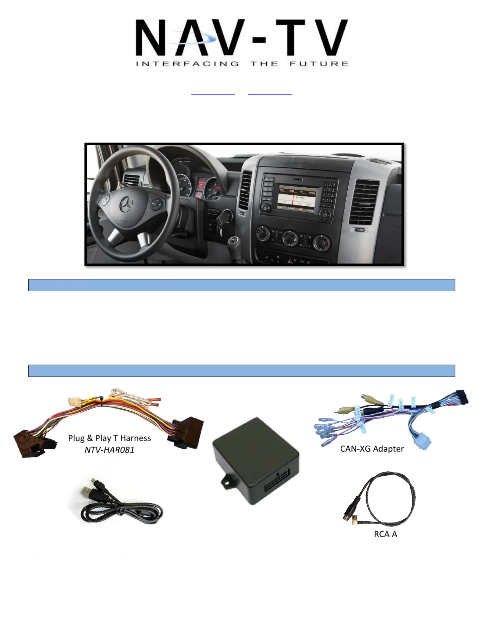
MB Sprinter-CAM
NTV-KIT477
Overview
The MB Sprinter-CAM allows the user to add an aermarket rear camera to the factory screen on the
Mercedes Sprinter. If desired, forced camera is an opon through a mounted toggle switch (not included).
ATTENTION: This module locks the VIN and can only be used on ONE vehicle at a me. to
Kit Contents
SMB todapter
NTV-CAB007
USB Cable (updates)
NTV-CAB009
MB Sprinter-CAM
Module
NTV-ASY171
NTV-HAR058
Produktspecifikationer
| Varumärke: | NAV-TV |
| Kategori: | Dashcam |
| Modell: | NTV-KIT483 |
| Kraftkälla: | Batterij/Accu |
| Typ produkt: | Slagmoersleutel |
Behöver du hjälp?
Om du behöver hjälp med NAV-TV NTV-KIT483 ställ en fråga nedan och andra användare kommer att svara dig
Dashcam NAV-TV Manualer

5 Augusti 2025
4 Augusti 2025
4 Augusti 2025
29 Juli 2024
29 Juli 2024
29 Juli 2024
29 Juli 2024
29 Juli 2024
29 Juli 2024
29 Juli 2024
Dashcam Manualer
Nyaste Dashcam Manualer
11 Mars 2026
11 Mars 2026
3 Mars 2026
2 Februari 2026
23 Oktober 2025
19 Oktober 2025
15 Oktober 2025
14 Oktober 2025
14 Oktober 2025
14 Oktober 2025