Optex OVS-50TNR Bruksanvisning
Optex ej kategoriserat OVS-50TNR
Läs gratis den bruksanvisning för Optex OVS-50TNR (7 sidor) i kategorin ej kategoriserat. Guiden har ansetts hjälpsam av 25 personer och har ett genomsnittsbetyg på 4.8 stjärnor baserat på 2 recensioner. Har du en fråga om Optex OVS-50TNR eller vill du ställa frågor till andra användare av produkten? Ställ en fråga
Sida 1/7
- 1 -
FEATURES
This symbol requires an action or gives an instruction.
This symbol indicates recommendation.
INTRODUCTION
1
1-1
BEFORE YOUR OPERATION
No. 59-2882-1
INSTALLATION INSTRUCTIONS
MODEL
OVS-50TNR
DETECTION RANGE
50 ft. / 15 m
• Slim body design
• Easy to see LED optical alignment
• IP65 waterproof structure
• Outdoor use / Usage extérieur
• Easy installation with battery driven transmitter
• 8 years battery life with 2pcs. of SAFT LSH-20
• Simplified optical adjustment -Sniper View Finder with ×2 magnification
Warning
Caution
Indicates a potentially hazardous situation which, if not avoided,
will result in minor or moderate injury, or may result in serious
injury or death.
Additionally there may be significant property damage.
Indicates a potentially hazardous situation which, if not avoided,
may result in minor or moderate injury or in property damage.
This symbol indicates prohibition. The specific prohibited action is provided in
and/or around the figure.
BATTERY OPERATED
PHOTOELECTRIC DETECTOR
OVS-50TNR
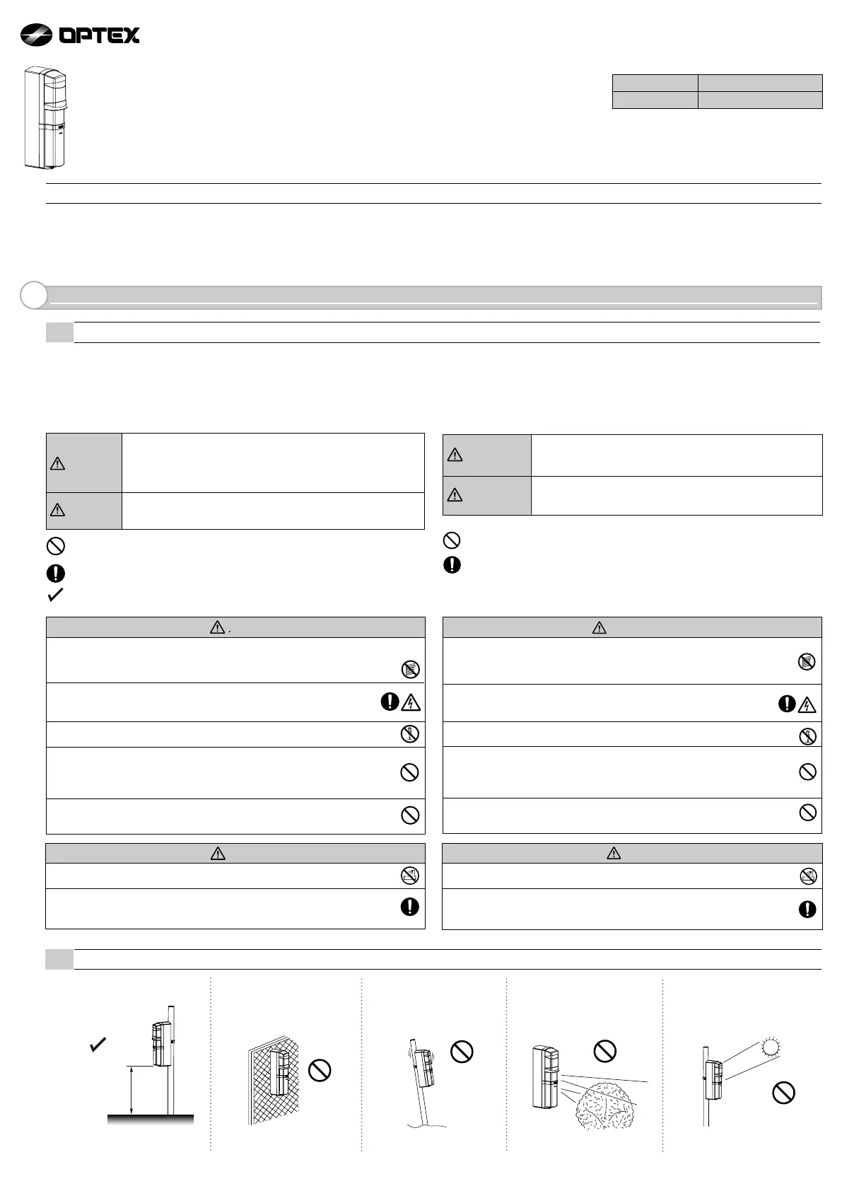
1-2 PRECAUTIONS
Do not install the unit on an unstable
surface.
Do not install the pole in a location
where sufficient stability can not be
ensured.
Do not install the unit in trees, leaves,
or other objects that may swing in the
wind and block the beam.
Avoid installing the receiver in a location
where rising or setting sun may go
directly into the receiver.
Install the unit at 13” height from the
ground level.
13” ± 2”
(330 ± 50 mm)
※
No less than 11”
・
The system must install in ordinary locations in accordance with the in Canada general requirements are given in CSA Standard C22.2 No.0, General Requirements
– Canadian Electrical Code, Part II.
• Read this instruction manual carefully prior to installation.
• After reading, store this manual carefully in an easily accessible place for reference.
• This manual uses the following warning indications for correct use of the product, harm to you or other people and damage to your assets, which are described below.
Be sure to understand the description before reading the rest of this manual.
Ce symbole signifie interdiction. L'action interdite est décrite dans et/ou autour de l'image.
Ce symbole demande une action ou donne une instruction.
Avertissement
Attention
Le non respect des instructions indiquées par signe et un
mauvais maniement peuvent causer la mort ou des blessures
graves.
Le non respect des instructions indiquées par ce signe et un
mauvais maniement peuvent causer des blessures et/ou des
dommages matériels.
Caution
Do not pour water over the product with a bucket, hose, etc. The water may
enter, which may cause damage to the devices.
Clean and check the product periodically for safe use. If any problem is found, do not
attempt to use the product as it is and have the product repaired by a professional
engineer or electrician.
Attention
Ne pas verser d'eau sur le produit avec un seau, un tuyau, etc. De l'eau
pourrait pénétrer et endommager l'appareil.
Nettoyer et vérifier périodiquement le produit pour une utilisation en toute
sécurité. Si vous rencontrez un problème, n'essayez pas d'utiliser le produit
en l'état, faites le réparer par un ingénieur ou électricien professionnel.
Warning
Do not use this product for any other purpose other than its intended use on automatic gates.
This product is not intended for use on Industrial Doors or Vertical gates and does not comply
with UL 325 for those applications.
Do not touch the unit base or power terminals of the product with a wet
hand (do not touch when the product is wet with rain, etc.). It may cause
electric shock.
Never attempt to disassemble or repair the product. It may cause fire or
damage to the devices.
Do not use batteries that have different levels of power remaining (i.e., new and
used batteries). Not observing the above may result in an explosion, leakage of
electrolyte, emission of toxic gases or other outcomes that may be harmful to
people and property.
[Handling of Batteries] Do not recharge, short circuit, crush, disassemble, exceed heat
above 100°C (212°F), incinerate, or expose contents to water. Do not solder directly to
the cell.
Avertissement
Ne jamais essayer de démonter ou de réparer le produit. Cela pourrait
causer un incendie ou endommager le dispositif.
Ne pas utiliser des batteries avec des niveaux de charges différents
(par ex., des batteries neuves avec des usagées). Le non respect de ce
qui précède peut causer une explosion, une fuite d'électrolyte, une émission
de gaz toxiques ou une conséquence nocive aux personnes et aux biens.
[Manipulation des batteries] Ne pas recharger, court-circuiter, écraser,
démanteler, porter à une température supérieure à 100°C (212°F), incinérer,
ou exposer le contenu à de l’eau. Ne pas souder directement à la cellule.
Ne pas toucher l'unité ou les bornes électriques du produit avec une main
humide (ne pas toucher si le produit a été mouillé par la pluie, etc.).
Il y a un risque de choc électrique.
N'utilisez pas ce produit à d'autres fins que son utilisation prévue sur les
portails automatiques. Ce produit n'est pas destiné à être utilisé sur des
portes industrielles ou des portails verticaux et n'est pas conforme à la
norme UL 325 pour ces applications.
Produktspecifikationer
| Varumärke: | Optex |
| Kategori: | ej kategoriserat |
| Modell: | OVS-50TNR |
Behöver du hjälp?
Om du behöver hjälp med Optex OVS-50TNR ställ en fråga nedan och andra användare kommer att svara dig
ej kategoriserat Optex Manualer

6 Oktober 2025
9 September 2025
4 September 2025
3 September 2025
3 September 2025
3 September 2025
3 September 2025
3 September 2025
3 September 2025
3 September 2025
ej kategoriserat Manualer
Nyaste ej kategoriserat Manualer
3 April 2026
3 April 2026
3 April 2026
3 April 2026
3 April 2026
3 April 2026
3 April 2026
3 April 2026
3 April 2026