Optex SIP-404 Bruksanvisning
Optex ej kategoriserat SIP-404
Läs gratis den bruksanvisning för Optex SIP-404 (12 sidor) i kategorin ej kategoriserat. Guiden har ansetts hjälpsam av 20 personer och har ett genomsnittsbetyg på 5.0 stjärnor baserat på 6 recensioner. Har du en fråga om Optex SIP-404 eller vill du ställa frågor till andra användare av produkten? Ställ en fråga
Sida 1/12
- 1 -
ENGLISHFRANÇAISDEUTSCHITALIANOESPAÑOL
2.3-4.0 m
(7.6-13 ft.)
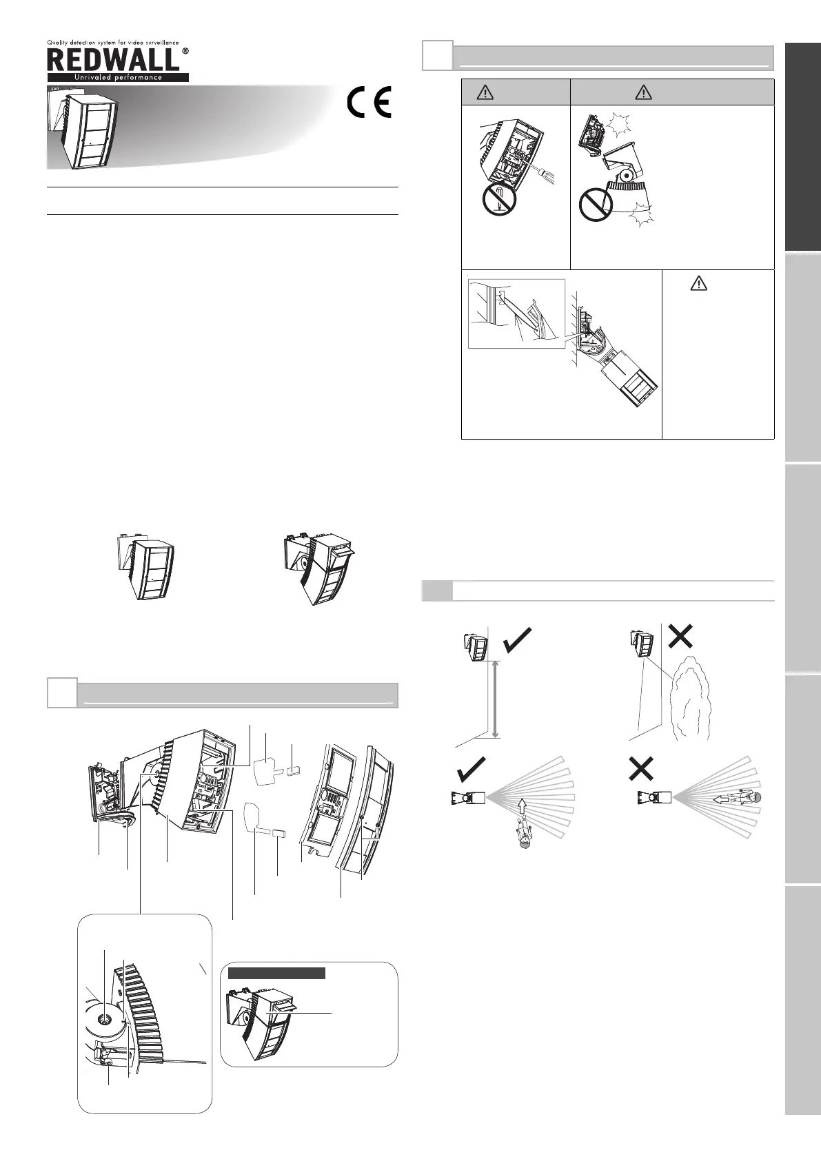
INSTALLATION AND MAINTENANCE NOTES
WarningCaution
Never repair or
modify product
Hold the main unit
securely when you
install or service it.
If you remove your
hands from the main
unit when cables are
connected to it, the
main unit may fall
and the connector
cables may break
or the circuit board
may be damaged.
Caution
Verify that the
power is off before
connecting the
wiring.
2
PARTS IDENTIFICATION
1
No. 59-1494-2 0911-01
INSTALLATION INSTRUCTIONS
Synthesized Intelligent PIR
REDWALL-V series
Synthesized Intelligent PIR
REDWALL-V series
FEATURES
* Intelligent PIR Detection System
- Detection of ambient temperature and illuminance for
automatic sensitivity management
- Advanced detection algorithm
- Three dual pyro-elements with patented Double Conductive
Shielding
* Anti-vandalism functions
- Anti-rotation function with 3-axis accelerometer
- Anti-masking function with photo-beam
- Reinforced polycarbonate housing
- Max. 4 m (13 ft.) installation height
* Independent sensitivity selector for near/far areas
* Detection logic selector
* Detection range selector
* Independent N.C. and N.O. outputs
* Adjustable alarm interval time
• SIP-3020CAM DN (EU), SIP-3020CAM DN (US)
* High-quality camera image: Day (colour)/Night (B/W)
* 480 TV lines
* Varifocal lens 3-9 mm
* Minimum illumination: Day (colour) 0.5 lx, Night (B/W): 0.03 lx
REDWALL-VREDWATCH-V
: Synthesized Intelligent PIR
SIP-3020
SIP-4010
SIP-404
•
•
•
: Synthesized Intelligent PIR
with D/N camera
SIP-3020CAM DN (EU)
SIP-3020CAM DN (US)
•
•
SIP-3020CAM DN
Mount the detector so that the majority of traffi c fl ow is across the detection pattern.
*1: Not used for the SIP-4010 and SIP-404.
2-1
INSTALLATION HINTS
Base
Fixing screw
for the base
Main unit
Masking plate for near
area (*1)
Fixing rubber
form (*1)
Window
Fixing screw
for the cover
Cover
Far area mirror
Masking plate for far area
Fixing rubber form
Adjustment screws
(two facing each other)
Angle adjustment guide
Camera unit
Near area mirror
Arrow marking
Fixing screw
Nylon wire
loop
When servicing, the sensor
can be hooked onto the
base using the nylon wire
loop.
REDWALL-VSIP-30204010404EN.i11REDWALL-VSIP-30204010404EN.i112009/10/2711:07:472009/10/2711:07:47
Produktspecifikationer
| Varumärke: | Optex |
| Kategori: | ej kategoriserat |
| Modell: | SIP-404 |
Behöver du hjälp?
Om du behöver hjälp med Optex SIP-404 ställ en fråga nedan och andra användare kommer att svara dig
ej kategoriserat Optex Manualer

6 Oktober 2025
9 September 2025
4 September 2025
3 September 2025
3 September 2025
3 September 2025
3 September 2025
3 September 2025
3 September 2025
3 September 2025
ej kategoriserat Manualer
Nyaste ej kategoriserat Manualer
3 April 2026
3 April 2026
3 April 2026
3 April 2026
3 April 2026
3 April 2026
3 April 2026
3 April 2026
3 April 2026