Shuttle XPC SA76R4 Bruksanvisning
Shuttle Inte kategoriserad XPC SA76R4
Läs gratis den bruksanvisning för Shuttle XPC SA76R4 (2 sidor) i kategorin Inte kategoriserad. Guiden har ansetts hjälpsam av 23 personer och har ett genomsnittsbetyg på 4.7 stjärnor baserat på 4 recensioner. Har du en fråga om Shuttle XPC SA76R4 eller vill du ställa frågor till andra användare av produkten? Ställ en fråga
Sida 1/2
12. Fasten the Smart Fan to the chassis with the 4 thumbscrews.
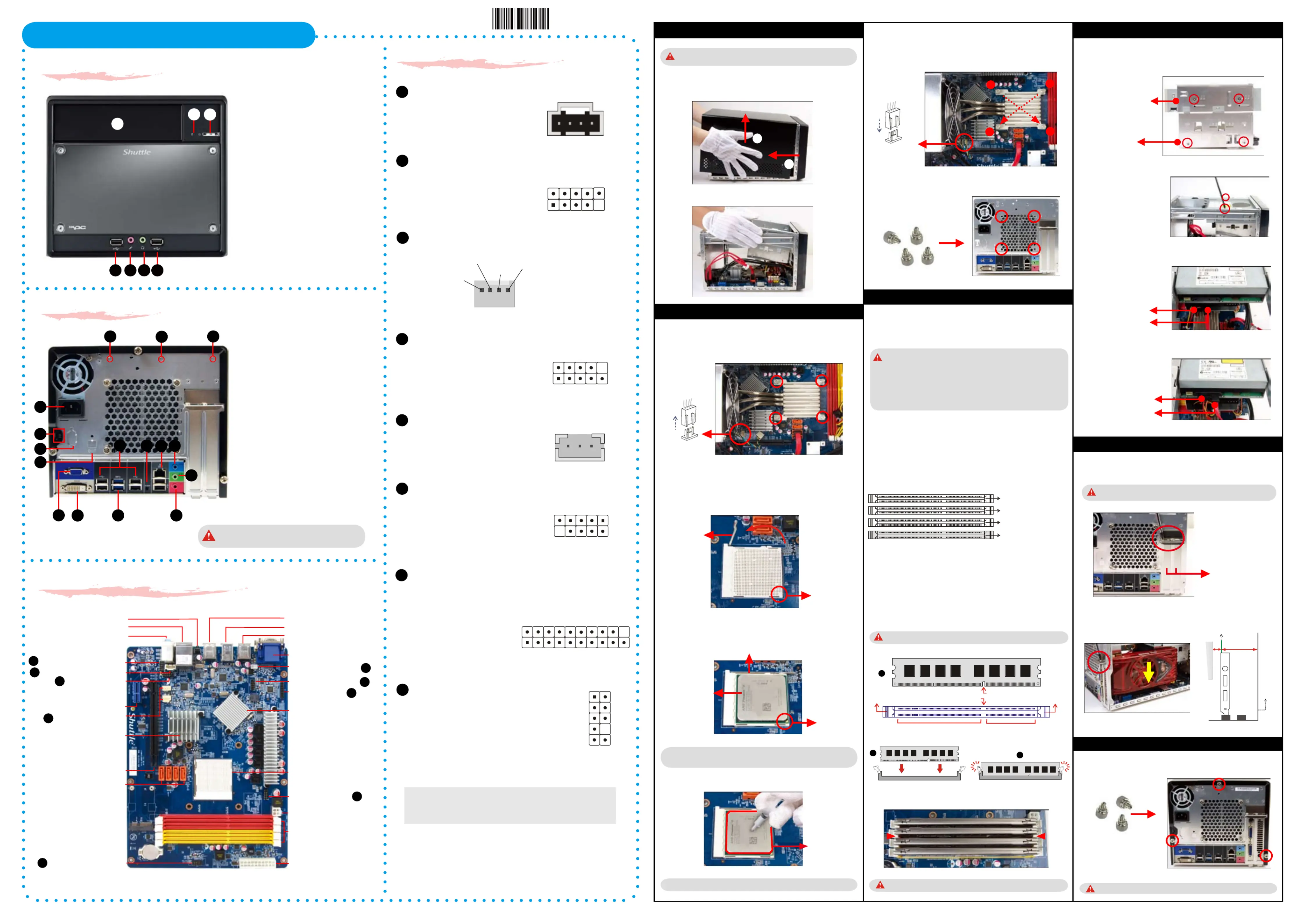
SA76R4 Quick Guide【 English 】
Jumper Settings
Motherboard Illustration
J5
SPDIF-Out Connector
_
(SPDIF1)
1=Ground
2=VCC
3=SPDIF_Out
Front Panel
Back Panel
J4
Power Button Connector_
(JP4)
A. Begin Installation
1. Unscrew 3 thumbscrews of the chassis cover.
2. Slide the cover backwards and upwards.
3. Unfasten the rack mount screws and remove the rack.
B. CPU and ICE Installation
For safety reasons, please ensure that the power cord is
disconnected before opening the case.
1. Unfasten the ICE fan thumbscrews on the back of the chassis.
2. Unfasten the four ICE module attachment screws and unplug the fan
connector.
1. Unlock the DIMM latch.
2. Align the memory module's cutout with the DIMM slot notch.
Slide the memory module into the DIMM slot.
C. Memory module Installation
3. Check that the latches are closed, and the memory module is firmly installed.
D. Peripheral Installation
1. Unfasten expansion slot bracket screws.
Remove the back panel bracket and put the bracket aside.
E. Accessories Installation
2. Install the PCI Express p1-x16 card into the PCI Express p1-x16 slot.
3. Secure the bracket.
F. Complete
Please load the optimized BIOS values.
Fan Connector
The maximum size acceptable for display card is
267mm x 98mm x 34.6mm
Safety Information
Read the following precautions before setting up a Shuttle XPC.
Laser compliance statement
The optical disc drive in this PC is a laser product.
The drive's classication label is located on the drive.
CLASS 1 LASER PRODUCT
CAUTION:INVISIBLE LASER RADIATION WHEN OPEN.
AVOID EXPOSURE TO BEAM.
CAUTION
Incorrectly replacing the battery may damage this computer.
Replace only with the same or equivalent as recommended by Shuttle.
Dispose of used batteries according to the manufacturer's instructions.
1. Replace the cover and refasten the thumbscrews.
2. Complete.
5. Connect the Serial ATA and power cables to the optical drive.
Serial ATA HDD
Channel A, DIMM1 (Red)
Channel B, DIMM2 (Red)
Channel A, DIMM3 (Yellow)
Channel B, DIMM4 (Yellow)
Make sure that the motherboard supports the memory.
It is recommended that memory of the same capacity, brand, speed,
and chips be used.
(Go to Shuttle's website for the latest memory support list.)
Memory modules have a foolproof design. A memory module can
be installed in only one direction. If you are unable to insert the
memory, switch the direction.
This motherboard provides four DDR3 memory sockets and supports Dual
Technology. After the memory is installed, the BIOS will automatically
detect the specifications and capacity of the memory.
Dual Channel memory mode may double the original memory bandwidth.
You may install varying memory sizes, the system maps the total size of
the lower-sized channel for the dual-channel configuration. Any excess
memory from the higher-sized channel is then mapped for single-channel
operation.
Guidelines for Memory Conguration
Before installing DIMMs, read and follow these guidelines for memory
configuration.
Installing a Memory
DDR3 DIMMs are not compatible to each other or DDR DIMMs.
Be sure to install DDR3 DIMMs on this motherboard. Follow the steps below
to correctly install your memory modules in the memory sockets.
Repeat to install additional memory modules if required.
Cutout
Latch
Latch
Notch
DDR3 240-pin 1.5V
48*2=96 pin
72*2=144 pin
A DDR3 memory module has a cutout, so it can only fit in one direction.
10. Screw the ICE module to the mainboard. Note to press down on the
opposite diagonal corner while tightening each screw.
11. Connect the fan connector.
Fan Connector
Follow the steps below to correctly install the CPU into the
motherboard CPU socket.
2
1
3
Serial ATA Cable
Serial ATA Power Cable
L
The product’s color and specification will depend upon the actually shipping product.
1
2
1
2
3
4
Serial ATA ODD
4. Connect the Serial ATA and power cables to the HDD.
Serial ATA Cable
Serial ATA Power Cable
PCI Express p1-x16 slots
4x 240 pins DDR3 DIMM Slots
Line-Out/Line-In Ports/
MIC Port
Clear CMOS Button
2x USB 2.0 Ports
ATX Power Connector-ATX1
PCI Express p1-x16 Slots
DVI-D Port & VGA Port
AUX IN Connector-AUX_IN1
J3
J4
J5
J2
2x USB 3.0 Ports
J3
4PIN FAN connector_
(CPU Fan,SYS Fan)
SPEED_SENSE
PWM_CTRL
+12V
Ground
CPU FAN , SYS FAN
3 2 1
2 4 6 8 10
2. Place the HDD and optical drive in the rack and secure with screws
from the side.
3. Place the rack in the chassis and refasten the rack.
1. Loosen the purse lock and separate the Serial ATA and power cables.
SPDIF-Out Connector
-SPDIF1
Serial ATA-SATA 1,2,3,4
J7
Power Button Connector
-JP4
J1
USB Header
_
(USB2,USB3)
1=5V 2=5V
3=USB6- 4=
USB7-
5=USB6+ 6=USB7+
7=GND 8=GND
9=NA 10=GND
J2
J1
AUX IN Connector
_
(AUX_IN1)
1=CD_IN_L
2=Ground
3=Ground
4=CD_IN_R
4 3 2 1
J6
Com Connector
_
(COM1)
1=DCD 2=RX
3=TXD 4=DTR
5=Ground 6=DSR
7=RTS 8=CTS
9=-XRI 10=NUUL
9 7 5 3 1
10 8 6 4 2
J7
LPC Header
_
(JP1)
J6
53R-SA76R3-3001
4PIN FAN connector_
(CPU Fan,SYS Fan)
F1. HDD LED
F2. Power Button / Power LED
F3. 5.25” Bay
F4. USB2.0 Ports
F5. Microphone
F6. Headphone
F1
F4
F3
F4F5
F6
F2
B1. AC Power Socket
B2. Kensington Lock
B3.
Serial Port
Perforation
(Optional)
B4. SPDIF Out Port
(Optional)
B5. VGA Port
B6. DVI-D Port
B7. USB3.0 Ports
B8. Microphone Jack
B9. Line-Out Jack
B10. Line-In Jack
B11. LAN & USB2.0 Ports
B12. Clear CMOS
Button
B13. USB2.0 Ports
B14.
Wireless LAN
Perforation
B8
B6
B1
B7
B10
B14
B5
B9
B11
B14
B2
B3
B14
B12
B13
B4
DVI-D & VGA Ports cannot be used, if the
PCI Express graphics card is installed.
4. Pull up the CPU socket lever to 90-degrees.
6. Spread an even layer of thermal compound on the CPU die.
Note: Failure to correctly align the CPU and socket can result in
damage to the CPU.
Note: Please do not use too much Heatsink compound.
AMD Processor
Triangle Markings
Lever
3. Remove the ICE module from the chassis and put it aside.
5. Match the yellow triangle on a corner of the CPU with the triangle on
the socket corner and gently insert the CPU into the socket and press
down the CPU socket lever.
Triangle Markings
Lever
Thermal Paste
application area
2x USB 2.0 Ports
2x USB 2.0 Ports & 1x LAN
ATX Power Connector-PWR1
One PCI Express p1-x1 Slot
AM3 Socket (941PIN)
ATI SB710 Chipset
ATI RS760 Chipset
USB Header-USB2
LPC Header-JP1
COM Connector-COM1
USB Header-USB3
J2
1=+HD_LED 2=PWR_LED
3=-HD_LED 4=
GND
5=RST_SW 6=PWR_SW
7=GND 8=GND
9=NA 10=GND
1 3 5 7 9
2 4 6 8 10
1 3 5 7 9
11 12 13 14 15 16 17 18 19
1 2 3 4 5 6 7 8 9 10
1=+12V 11=-12V
2=5V 12=+3V_DUAL
3=+5V_DUAL 13=RI-
4=SERIRQ 14=LDRQ-
5=CLK_LPC48M 15=LPC_PME-
6=CLK_LPC33M 16=LAD1
7=SIO_RST- 17=LAD0
8=LFRAME- 18=+3.3V
9=LAD3 19=GND
10=LAD2
FRONT audio connector-JP2
J8
J8
FRONT audio connector_
(JP2)
1=MIC2_L 2=AGND
3=MIC2_R 4=FRONT-JD
5=LINE2-R 6=SENSE1_RETURN
7=FRONT_SENSE 8=NUUL
9=LINE2-L 10=SENSE2_RETURN
1
3
5
7
9
2
4
6
8
10
VGA Card PCB
Chassis
Cover
5mm
34.6mm
PCI Express p1-x16 slots / PCI
62R-SA76R0-1501
English.Spanish.Korean.
Traditional Chinese.Japanese.
French. German Quick Guide
Produktspecifikationer
| Varumärke: | Shuttle |
| Kategori: | Inte kategoriserad |
| Modell: | XPC SA76R4 |
| Vikt: | 3200 g |
| Bredd: | 215 mm |
| Djup: | 325 mm |
| Höjd: | 190 mm |
| Strömförsörjning: | 100 - 240V |
| LED-indikatorer: | HDD, Power |
| Processorfamilj: | AMD |
| Wi-Fi: | Nej |
| Ljudsystem: | IDT 92HD89C |
| DVI-port: | Ja |
| Hörlursutgångar: | 1 |
| Certifiering: | EMI: FCC, CE, BSMI, C-Tick |
| Internminne: | 0 GB |
| Inbyggd kamera: | Nej |
| Maximalt internminne: | 16 GB |
| Ljudutgångskanaler: | 5.1 kanaler |
| Säkerhet: | ETL, CB, BSMI, TÜV |
| S/PDIF-utgång: | Ja |
| Mini PCI Express-kortplatser: | 1 |
| Kompatibla processorer: | AMD Phenom, AMD Phenom II Dual-Core Mobile, AMD Phenom II Triple-Core Mobile, AMD Phenom II X2, AMD Phenom II X3 |
| Minnestyper som stöds: | DDR3-SDRAM |
| Antal minnesplatser: | 4 |
| Moderkort: | FA76 V3.0 |
| Drive bays: | 1 x 5.25", 2 x 3.5" |
| Produktens färg: | Svart |
| Inbyggd kortläsare: | Nej |
| Tv-ut: | Nej |
| Nätverksegenskaper: | Gigabit Ethernet |
| Installerat operativsystem: | Nej |
| Antal LAN (RJ-45) anslutningar: | 1 |
| Produktstorlek (BxDxH): | 215 x 325 x 190 mm |
| processorsockel: | Socket AM2+/AM3 |
| Seriella portar: | 1 |
| Hållbarhetscertifiering: | ENERGY STAR |
| Material, hölje: | Acrylic, Aluminium |
| Nätverksansluten (Ethernet): | Ja |
| På / av-knapp: | Ja |
| Antal USB 2.0 anslutningar: | 12 |
| Minnesplatser, typ: | DIMM |
| Minnets hastigheter: | 1066,1333 MHz |
| Antal USB 3.2 Gen 1 (3.1 Gen 1) typ A-portar: | 2 |
| BIOS minnesstorlek: | 32 mbit |
| LAN-styrenhet: | Realtek RTL8111E |
| Moderkortets chipset: | AMD 760G |
| Externa anslutningar: | 4x SATA 3Gb/s |
| Kvalitet på VGA (D-Sub) porten: | 1 |
| Grafikadapterfamilj: | AMD |
| Ombord grafikkort modell: | AMD Radeon HD 3000 |
| Ombord grafikkort: | Ja |
| Uttag för mikrofon/linje in: | Ja |
| Typ av CardBus PCMCIA-kortplats: | Nej |
| Kylning typ: | Aktiv |
| PCI Express x16 platser: | 1 |
| PCI Express x1 kortplatser: | 1 |
| Processorfrekvens (max): | 2.6 GHz |
| Intern masslagringsenhet: | AMD 760 (880) + SB710 |
Behöver du hjälp?
Om du behöver hjälp med Shuttle XPC SA76R4 ställ en fråga nedan och andra användare kommer att svara dig
Inte kategoriserad Shuttle Manualer

16 September 2024
28 Augusti 2024
18 Augusti 2024
17 Augusti 2024
15 Augusti 2024
13 Augusti 2024
11 Augusti 2024
10 Augusti 2024
9 Augusti 2024
8 Augusti 2024
Inte kategoriserad Manualer
Nyaste Inte kategoriserad Manualer
9 April 2025
9 April 2025
9 April 2025
9 April 2025
9 April 2025
9 April 2025
9 April 2025
9 April 2025
9 April 2025
9 April 2025