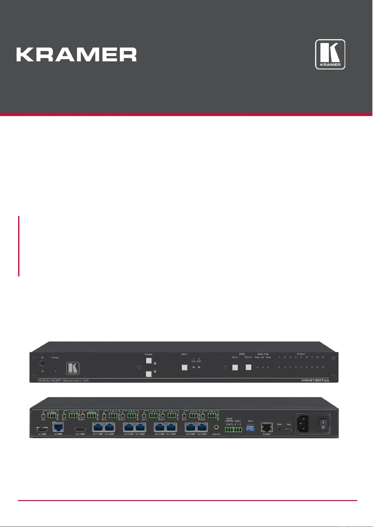
Kramer VM-218DT Bruksanvisning
Kramer
AV förlängare
VM-218DT
Läs gratis den bruksanvisning för Kramer VM-218DT (51 sidor) i kategorin AV förlängare. Guiden har ansetts hjälpsam av 40 personer och har ett genomsnittsbetyg på 4.3 stjärnor baserat på 20.5 recensioner. Har du en fråga om Kramer VM-218DT eller vill du ställa frågor till andra användare av produkten? Ställ en fråga
Sida 1/51

Kramer Electronics Ltd.
VM-218DTxr, VM-218DT – Contents
i
Contents
Introduction 1
Getting Started 1
Overview 2
Typical Applications 4
Controlling your VM-218DTxr 4
Defining VM-218DTxr HDMI/HDBT Switcher DA 5
Mounting VM-218DTxr 7
Connecting the HDMI/HDBT Switcher DA 8
Connecting VM-218DTxr 8
Connecting VM-218DT 9
Extending Control Signals 10
Controlling VM-218DTxr via RS-232 CONTROL 12
Wiring the RJ 45 Connectors 12
Setting the DIP-switches 13
Cascading Devices 14
Operating and Controlling the VM-218DTxr 15
Using the Front Panel Buttons 15
Acquiring the EDID 15
Using the Ethernet 16
Using the Embedded Web Pages 20
Browsing VM-218DTxr Web Pages 20
Switching the Inputs and Setting the Output Volume 22
Defining Video and Audio Settings 23
Setting the Output Labels 24
Managing EDID 24
Setting Web Page Access Permission 29
Changing Device Settings 31
Upgrading the Firmware 33
Viewing the About Page 34
Upgrading the Firmware 35
Technical Specifications
36
Default Communication Parameters
37
Default EDID 38
Protocol 3000 40
Understanding Protocol 3000 40
Protocol 3000 Commands 41
Result and Error Codes 47

Kramer Electronics Ltd.
VM-218DTxr, VM-218DT – Introduction
1
Introduction
Welcome to Kramer Electronics! Since 1981, Kramer Electronics has been providing a world
of unique, creative, and affordable solutions to the vast range of problems that confront the
video, audio, presentation, and broadcasting professional on a daily basis. In recent years, we
have redesigned and upgraded most of our line, making the best even better!
Getting Started
We recommend that you:
• Unpack the equipment carefully and save the original box and packaging materials for
possible future shipment.
• Review the contents of this user manual.
Go to www.kramerav.com/downloads/VM-218DTxr to check for up-to-date user manuals,
application programs, and to check if firmware upgrades are available (where appropriate).
Achieving the Best Performance
• Use only good quality connection cables (we recommend Kramer high-performance,
high-resolution cables) to avoid interference, deterioration in signal quality due to poor
matching, and elevated noise levels (often associated with low quality cables).
• Do not secure the cables in tight bundles or roll the slack into tight coils.
• Avoid interference from neighboring electrical appliances that may adversely influence
signal quality.
• Position your Kramer VM-218DTxr / VM-218DT away from moisture, excessive sunlight
and dust.
Safety Instructions
Caution:
• This equipment is to be used only inside a building. It may only be connected to other
equipment that is installed inside a building.
• For products with relay terminals and GPI\O ports, please refer to the permitted rating
for an external connection, located next to the terminal or in the User Manual.
• There are no operator serviceable parts inside the unit.
Warning:
• Use only the power cord that is supplied with the unit.
• Disconnect the power and unplug the unit from the wall before installing.
• Do not open the unit. High voltages can cause electrical shock! Servicing by qualified
personnel only.
• To ensure continuous risk protection, replace fuses only according to the rating
specified on the product label which located on the bottom of the unit.

Kramer Electronics Ltd.
VM-218DTxr, VM-218DT – Defining VM-218DTxr HDMI/HDBT Switcher DA
5
Defining VM-218DTxr HDMI/HDBT
Switcher DA
VM-218DTxr and VM-218DT appear identical.
This section defines VM-218DTxr.
Figure 1: VM-218DTxr HDMI/HDBT Switcher DA Front Panel
#
Feature
Function
IR LED
Lights orange when the unit accepts IR remote commands.
IR Sensor
Use to control a peripheral device connected to OUT 2 HDBT with that
device’s remote controller.
POWER LED
Lights when the unit is powered.
VOLUME ()
Press to decrease the volume of the analog audio output.
VOLUME ()
Press to increase the volume of the analog audio output.
INPUT Selector Button
Press to select input 1 HDMI or input 2 HDBT.
INPUT LEDs
Lights green to indicate the selected input: 1 HDMI or 2 HDBT.
EDID READ Button
Press to read the selected EDID and write it to both inputs.
EDID SELECT Button
Press to cycle through the sources from which to read the EDID: Default,
External, or Output. When Output is selected, cycles through outputs 1 to 9.
The relevant EDID TYPE and OUTPUT LEDs light green.
EDID TYPE LEDs
Lights green to indicate the selected EDID type: DEFAULT, EXT. (external)
or OUTPUT.
OUTPUT LEDs (1 to 9)
In normal operation mode: lights green when an acceptor is connected to the
output.
In EDID mode: when EDID TYPE OUTPUT LED lights green, press the
EDID SELECT button briefly to cycle through output 1 to 9 to select the
output from which to read EDID. The relevant LED lights during EDID setup
and remains lit after completing the EDID setup.

Kramer Electronics Ltd.
VM-218DTxr, VM-218DT – Defining VM-218DTxr HDMI/HDBT Switcher DA
6
Figure 2: VM-218DTxr HDMI/HDBT Switcher DA Rear Panel
#
Feature
Function
IN 2 IR on a 3.5 Mini Jack
Connect to an IR emitter/sensor cable for IR link extension via IN 2
HDBT.
IN 2 RS-232 (G, Rx, Tx)
Terminal Block Connector
Connect to a serial controller for RS-232 link extension via IN 2 HDBT.
IN 1 HDMI Connector
Connect to an HDMI source.
IN 2 HDBT on RJ-45
Connectors
Connect to an HDBT transmitter (for example: TP-780Txr for
VM-218DTxr and TP-580T for VM-218DT).
IR on 3.5 Mini Jacks (for
OUT 2 to 9)
Connect to remote IR emitter/sensor cables to IR control the devices that
are connected to the HDBT acceptors.
RS-232 OUT (G, Rx, Tx)
Terminal Block Connectors
(2 to 9)
Connect to serially control the devices connected to the HDBT acceptors.
OUT 1 HDMI Connector
Connect to the HDMI input of an additional DA or connect to a local
monitor.
OUT HDBT RJ-45
Connectors (2 to 9)
Connect to HDBT receivers (for example: TP-780Rxr for VM-218DTxr
and TP-580R for VM-218DT).
AUDIO OUT 3.5mm Mini
Jack
Connect to an analog audio acceptor.
RS-232 CONTROL 3-pin
Terminal Block
Connect to the serial controller to control the VM-218DTxr.
REMOTE 3-pin Terminal
Block
For future use.
SETUP DIP-switches
Use to set the device behavior.
ETHERNET RJ-45
Connector
Connect to LAN for Ethernet extension via IN and OUT HDBT ports and
remote IP control of the VM-218DTxr.
RESET Button
Press and hold while powering on the device to reset to factory default
parameters.
PROG Mini USB Connector
Connect to a PC to perform firmware upgrades.
Mains Power Connector,
Fuse and Switch
Connect to the mains supply.

Kramer Electronics Ltd.
VM-218DTxr, VM-218DT – Mounting VM-218DTxr
7
Mounting VM-218DTxr
This section provides instructions for mounting VM-218DTxr. Before installing, verify that the
environment is within the recommended range:
• Operation temperature – 0 to 40C (32 to 104F).
• Storage temperature – -40 to +70C (-40 to +158F).
• Humidity – 10% to 90%, RHL non-condensing.
Caution:
• Mount VM-218DTxr before connecting any cables or power.
Warning:
• Ensure that the environment (e.g., maximum ambient temperature & air flow) is
compatible for the device.
• Avoid uneven mechanical loading.
• Appropriate consideration of equipment nameplate ratings should be used for avoiding
overloading of the circuits.
• Reliable earthing of rack-mounted equipment should be maintained.
To mount the VM-218DTxr in a rack:
Attach both rack ears by removing the screws from each side of the
machine and replacing those screws through the rack ears or place
the machine on a table.
For more information go to www.kramerav.com/downloads/VM-218DTxr

Kramer Electronics Ltd.
VM-218DTxr, VM-218DT – Connecting the HDMI/HDBT Switcher DA
8
Connecting the HDMI/HDBT
Switcher DA
Although both the VM-218DTxr and VM-218DT appear identical, the VM-218DTxr also
extends Ethernet signals, therefore the connecting procedures in this section are described
separately for each device.
Always switch off the power to each device before connecting it to your VM-218DTxr. After
connecting your VM-218DTxr, connect its power and then switch on the power to each
device.
Connecting VM-218DTxr
Figure 3: Connecting to VM-218DTxr
To connect the VM-218DTxr as illustrated in the example in Figure 3:
1. Connect an HDMI source (for example, a Blu-ray player) to the IN 1 HDMI connector .
2. Connect an HDBT transmitter (for example, Kramer TP-780Txr) to the IN 2 HDBT RJ-45
connector .
3. Connect the OUT 1 HDMI connector to an HDMI acceptor (for example, a display).
4. Connect the 8 OUT HDBT RJ-45 connectors (2 to 9) to up to 8 HDBT receivers (for
example, Kramer TP-780Rxr receivers).
5. Connect the AUDIO OUT 3.5mm mini jack to an analog audio acceptor (for example,
Kramer Tavor 6-O speakers).
6. Connect the RS-232 terminal block connector to a serial control device (for example,
a laptop) to control VM-218DTxr.
7. Connect the Ethernet RJ-45 port to the Ethernet LAN to control the VM-218DTxr and
LAN-connected peripheral devices, either local LAN or through input HDBT extended

Kramer Electronics Ltd.
VM-218DTxr, VM-218DT – Connecting the HDMI/HDBT Switcher DA
9
Ethernet, via IP control device (for example, a laptop) and/or an IP room controller (for
example, Kramer SL-240C).
8. Connect the power adapter to the VM-218DTxr and to the mains electricity (not
shown in Figure 3).
9. Connect signal extensions (see Extending Control Signals on page 10).
The USB connector and power cord are not shown in Figure 3.
Connecting VM-218DT
Figure 4: Connecting to VM-218DT
To connect the VM-218DT as illustrated in the example in Figure 4:
1. Connect an HDMI source (for example, a Blu-ray player) to the IN 1 HDMI connector .
2. Connect an HDBT transmitter (for example, Kramer TP-580T) to the IN 2 HDBT RJ-45
connector .
3. Connect the OUT 1 HDMI connector to an HDMI acceptor (for example, a display).
4. Connect the 8 OUT HDBT RJ-45 connectors (2 to 9) to up to 8 HDBT receivers (for
example, Kramer TP-580R receivers).
5. Connect the AUDIO OUT 3.5mm mini jack to an analog audio acceptor (for example,
Kramer Tavor 6-O speakers).
6. Connect the RS-232 terminal block connector to a serial control device (for example,
a laptop) to control the VM-218DT.
7. Connect the Ethernet RJ-45 port to the Ethernet LAN to control the VM-218DT and
its peripheral devices and/or to a room controller (for example, Kramer
SL-240C).
8. Connect the power adapter to the VM-218DT and to the mains electricity (not shown
in Figure 4).

Kramer Electronics Ltd.
VM-218DTxr, VM-218DT – Connecting the HDMI/HDBT Switcher DA
11
In the same way you can pass IR signals to control other connected peripheral devices using
the IR ports of the VM-218DTxr, HDBT transmitter and HDBT receivers.
RS-232 Extension
Use the RS-232 3-pin terminal block connectors for the HDBT input and outputs to
extend RS-232 control signals between any set of RS-232 ports on the HDBT transmitter and
receivers.
To extend an RS-232 signal, for example, from VM-218DTxr to Projector B:
1. Connect OUT 5 RS-232 3-pin terminal block connector to a room controller (for example,
the Kramer SL-240C room controller.
2. Connect the RS-232 port on the TP-780Rxr receiver (that is connected to HDBT OUT 5)
to Projector B.
3. Send an RS-232 command from the room controller to Projector B.
In the same way you can control other peripheral devices that are connected to the
transmitter and/or receivers.
To extend an RS-232 signal, for example, from a remote room controller to Projector A:
1. Connect an RS-232 cable between a room controller (for example, Kramer SL-240C)
and the RS-232 port on the TP-780Txr transmitter that is connected to HDBT IN 2.
2. Connect an RS-232 cable between the IN 2 RS-232 3-pin terminal block connector and
the OUT 3 RS-232 3-pin terminal block connector.
3. Connect an RS-232 cable between the TP-780Rxr (that is connected to OUT 3 HDBT)
RS-232 port and Projector A.
4. Send an RS-232 command from the room controller to Projector A on the TP-780Rxr via
the HDBT IN 1 port.
In the same way you can send RS-232 commands to control other peripheral devices
connected to the transmitter/receivers.
In the same way you can send RS-232 signals and commands to control other peripheral
devices connected between the RS-232 ports of the VM-218DTxr, HDBT transmitter and
HDBT receivers.
Ethernet Extension (VM-218DTxr only)
Use the ETHERNET RJ-45 port input and outputs to extend Ethernet signals via
control devices and/or control software to and from the HDBT transmitter/receivers.
To send a command from a room controller, for example, to the display:
1. Connect the ETHERNET RJ-45 port to the Ethernet.
2. Connect the ETH port of a room controller (for example, the Kramer SL-240C room
controller) to the Ethernet.

Kramer Electronics Ltd.
VM-218DTxr, VM-218DT – Connecting the HDMI/HDBT Switcher DA
12
3. Send an RS-232 command from the room controller to the display on the TP-780Rxr via
the HDBT OUT 7 port.
In the same way you can control other peripheral devices connected to the
transmitter/receivers.
Controlling VM-218DTxr via RS-232 CONTROL
VM-218DTxr features an RS-232 CONTROL 3-pin terminal block connector allowing the
RS-232 to control the VM-218DTxr. To do so, connect the VM-218DTxr to a controller (for
example a PC) via the RS-232 CONTROL terminal block on the rear panel as follows:
• Pin 2 to the TX pin on the VM-218DTxr
RS-232 CONTROL terminal block.
• Pin 3 to the RX pin on the VM-218DTxr
RS-232 CONTROL terminal block.
• Pin 5 to the G pin on the VM-218DTxr
RS-232 CONTROL terminal block.
Wiring the RJ 45 Connectors
This section defines the HDBT pinout, using a straight pin-to-pin cable with RJ 45 connectors.
For HDBT cables, it is recommended that the cable ground shielding be connected/soldered
to the connector shield.
EIA /TIA 568B
PIN
Wire Color
1
Orange / White
2
Orange
3
Green / White
4
Blue
5
Blue / White
6
Green
7
Brown / White
8
Brown

Kramer Electronics Ltd.
VM-218DTxr, VM-218DT – Connecting the HDMI/HDBT Switcher DA
13
Setting the DIP-switches
Changes to the DIP-switches only take effect following power-up. After changing a switch,
reboot the device. All DIP-switches are set to Off (up) by default.
#
Feature
Dip-switch Settings
1
Reserved
2
Range mode
Off (up) – Normal range (default).
On (down) – HDBaseT Ultra-long range (provides increased range at
a reduced bandwidth).
Note that range mode affects the HDBT input only.
3
Audio de-embedding
Off (up) – Enable 2-channel uncompressed audio de-embedding to
the analog audio output port (default).
Note that compressed audio pass-through is disabled.
On (down) – Disable audio de-embedding and enable pass-through of
all audio formats.
Note that the analog audio output port is muted.
4
Force RGB
Off (up) – Normal mode (default).
On (down) – Force RGB mode.

Kramer Electronics Ltd.
VM-218DTxr, VM-218DT – Connecting the HDMI/HDBT Switcher DA
14
Cascading Devices
Use the OUT 1 HDMI connecter on VM-218DTxr to connect a local monitor or to
distribute the signal to an additional receiver, thus creating a 2x16 DA system as described in
the following example.
To cascade VM-218DTxr:
1. Connect the inputs and outputs to the primary device as described in Connecting the
HDMI/HDBT Switcher DA on page 8, except for the OUT 1 HDMI connector.
2. On the cascaded DA device, connect the receivers as required.
Connect the power to the receivers only after connecting them to the cascaded device.
3. Connect the OUT 1 HDMI connector on the primary device to the IN 1 HDMI connector
on the cascaded DA device.
4. After powering the cascaded device, make sure that the HDMI input is selected on the
cascaded device.
Figure 5: Cascading DAs
18
14

Kramer Electronics Ltd.
VM-218DTxr, VM-218DT – Operating and Controlling the VM-218DTxr
16
• EDID Designer software.
VM-218DTxr Supports EDID Designer (via the mini USB port) that can be
loaded from our Web site: Kramer EDID Designer.
To use the mini USB port, you need to download and the Kramer USB driver
from our Web site at: www.kramerav.com/support/product_downloads.asp and
install it.
Acquiring EDID via the Front Panel Buttons
The following procedure is usually done only once, when the device is being set up.
To acquire the EDID:
1. Press EDID SELECT repeatedly until the required EDID source is selected, (either
DEFAULT, EXT, or OUTPUT LED lights ).
When selecting OUTPUT, keep pressing repeatedly to select the desired output.
The relevant LED lights green.
2. Press EDID READ .
EDID READ flashes once and the EDID is copied to the currently selected input.
EDID READ flashing 3 times indicates that the EDID was not read.
The device reverts to the last stored EDID type, as indicated by the relevant EDID
TYPE LEDs.
If the EDID READ button is not pressed for five seconds, the procedure is terminated, the
device does not store a new EDID and the OUTPUT 1 to 9 LEDs revert to normal operation.
Forcing the RGB Mode
Normally (the default state), when acquiring EDID, the device supports any color space that is
defined in the acquired EDID parameters. In case of a color space problem, enabling Force
RGB mode may improve the colors of the image on the display.
Force RGB mode is enabled via the DIP-switches on the rear panel (see Setting the DIP-
switches on page 13).
Using the Ethernet
You can connect to the VM-218DTxr via Ethernet using either of the following methods:
• Locally, directly to the laptop using a crossover cable (see Connecting the Ethernet Port
Directly to a Laptop on page 17).
• Remotely over IP LAN, via a network hub, switch, or router, using a straight-through
cable (see Connecting the Ethernet Port via IP LAN on page 19).
Note: If you want to connect via a router and your IT system is based on IPv6, speak to your
IT department for specific installation instructions.

Kramer Electronics Ltd.
VM-218DTxr, VM-218DT – Operating and Controlling the VM-218DTxr
17
Connecting the Ethernet Port Directly to a Laptop
You can connect the Ethernet port of the VM-218DTxr directly to the Ethernet port on your
PC using a crossover cable with RJ-45 connectors.
This type of connection is recommended for identifying the VM-218DTxr
with the factory configured default IP address.
After connecting the VM-218DTxr to the Ethernet port, configure your PC as follows:
1. Click Start > Control Panel > Network and Sharing Center.
2. Click Change Adapter Settings.
3. Highlight the network adapter you want to use to connect to the device and click Change
settings of this connection.
The Local Area Connection Properties window for the selected network adapter appears
as shown in Figure 6.
Figure 6: Local Area Connection Properties Window
4. Highlight either Internet Protocol Version 6 (TCP/IPv6) or Internet Protocol Version 4
(TCP/IPv4) depending on the requirements of your IT system.
5. Click Properties.
The Internet Protocol Properties window relevant to your IT system appears as shown in
Figure 7 or Figure 8.

Kramer Electronics Ltd.
VM-218DTxr, VM-218DT – Operating and Controlling the VM-218DTxr
18
Figure 7: Internet Protocol Version 4 Properties Window
Figure 8: Internet Protocol Version 6 Properties Window
6. Select Use the following IP Address for static IP addressing and fill in the details as
shown in Figure 9.
For TCP/IPv4 you can use any IP address in the range 192.168.1.1 to 192.168.1.255
(excluding 192.168.1.39) that is provided by your IT department.

Kramer Electronics Ltd.
VM-218DTxr, VM-218DT – Operating and Controlling the VM-218DTxr
19
Figure 9: Internet Protocol Properties Window
7. Click OK.
8. Click Close.
Connecting the Ethernet Port via IP LAN
You can connect the Ethernet port of the VM-218DTxr, via IP LAN, to the Ethernet port on a
network hub or using a straight-through cable with RJ-45 connectors.
Configuring the Ethernet Port
You can set the Ethernet parameters via the embedded Web pages.

Kramer Electronics Ltd.
VM-218DTxr, VM-218DT – Using the Embedded Web Pages
21
3. Enter the User Name and Password (Admin, Admin) and click OK.
The Switching Web page appears (see Figure 11).
The VM-218DTxr Web pages enable performing the following:
• Switching the Inputs and Setting the Output Volume on page 22.
• Defining Video and Audio Settings on page 23.
• Setting the Output Labels on page 24.
• Managing EDID on page 24.
• Setting Web Page Access Permission on page 29.
• Changing Device Settings on page 31.
• Upgrading the Firmware on page 33.
• Viewing the About Page on page 34.

Kramer Electronics Ltd.
VM-218DTxr, VM-218DT – Using the Embedded Web Pages
22
Switching the Inputs and Setting the Output Volume
The Switching page enables performing the following functions:
• Switching the Inputs on page 22.
• Setting the Volume on page 22.
Switching the Inputs
To select an input to switch to the outputs:
1. In the Navigation pane, click Switching. The Switching page appears.
Figure 11: Switching Page with Navigation List on the Left
2. Click an input to route it to the outputs.
A green dot on the input button indicates that the input is connected and active.
3. Click to edit the input label name.
Setting the Volume
To set the analog audio volume:
1. In the Navigation pane, click Switching. The Switching page appears.
2. Use the slider to set the Analog Output Volume (0dB, by default).
3. If required, click to mute/unmute the output.

Kramer Electronics Ltd.
VM-218DTxr, VM-218DT – Using the Embedded Web Pages
23
Defining Video and Audio Settings
The Video and Audio Settings page enables performing the following functions:
• Setting the Power-Off Delay on page 23.
• Supporting HDCP Mode on page 23.
• Viewing Audio De-Embedding Status on page 24.
Setting the Power-Off Delay
When a signal is lost, you can set the output 5V power off delay time.
When 5V on the output is powered down, it indicates to the display connected to it that no
video signal is present.
To set the power-off delay time:
1. In the Navigation pane, click Video & Audio Settings. The Video & Audio Settings page
appears.
Figure 12: Video & Audio Settings Page
2. Set the delay time (900sec, by default).
3. Click Set.
The delay time is set.
Supporting HDCP Mode
To Enable/disable HDCP for each input:
1. In the Navigation pane, click Video & Audio Settings. The Video & Audio Settings page
appears.
2. Click Enable (default)/Disable per input.
Setting HDCP support to disabled on the HDMI input allows the source to transmit a
non-HDCP signal if required (for example, when working with a Mac computer).
HDCP mode is set per input.

Kramer Electronics Ltd.
VM-218DTxr, VM-218DT – Using the Embedded Web Pages
24
Viewing Audio De-Embedding Status
In the Navigation pane, click Video and Audio Settings to view the audio de-embedding
status as set by DIP-switch 3 (see Setting the DIP-switches on page 13).
Setting the Output Labels
Use the Output Settings page to label the different outputs. This can be very helpful (for
example, for supporting the system) since HDBT outputs 2 to 9 that are connected to
receivers can be identified easily on location.
To change an output label name:
1. In the Navigation pane, click Output Settings. The Output Settings page appears.
Figure 13: Output Settings Page
2. Type the new output label and click .
Managing EDID
Use the EDID page to read the EDID from:
▪ Any of the inputs.
▪ Any of the outputs.
▪ The default EDID.

Kramer Electronics Ltd.
VM-218DTxr, VM-218DT – Using the Embedded Web Pages
28
4. Click COPY.
The Input 2 EDID is copied to the selected inputs.
Figure 17: EDID Management Page – EDID Copied
Once the EDID is copied, a success message appears:
Figure 18: EDID Management Page – EDID Copied Successfully
5. Click OK.
To read the EDID from the default EDID:
1. In the Navigation pane, click EDID Management. The EDID Management page appears.
2. Click Default.
3. Select the input/s (or all the inputs) to which the default EDID is copied.
4. Click Copy and follow the instructions on-screen.

Kramer Electronics Ltd.
VM-218DTxr, VM-218DT – Using the Embedded Web Pages
29
To load an external EDID file:
1. In the Navigation pane, click EDID Management. The EDID Management page appears.
2. In the File area, click … to browse for the EDID file location.
3. Open the EDID file.
4. Select the input/s (or all the inputs) to which the EDID is copied.
5. Click Copy and follow the instructions on-screen.
Setting Web Page Access Permission
To define access permission to the web pages in the Navigation pane, click Authentication.
The Authentication page appears.
By default, the Web pages are secured (username and password are both Admin).
Figure 19: Authentication Page
To change the password:
1. In the Navigation pane, click Authentication. The Authentication page appears.
2. Type current password and then type the new password twice.
3. Click Change to store the new password. The following message appears:
Figure 20: Authentication – Reloading Web Page

Kramer Electronics Ltd.
VM-218DTxr, VM-218DT – Using the Embedded Web Pages
32
2. Set DHCP ON or OFF (default).
3. If DHCP is OFF, change any of the parameters (IP Address, Netmask and/or Gateway).
4. Click Set.
• After changing the IP Address, or DHCP to ON, reload the Web page with the new IP
address.
• After changing the Subnet mask, turn the VM-218DTxr power off and then on again.
Loading/Saving a Configuration
To Save a configuration file to your PC:
1. In the Navigation pane, click Device Setting. Device Settings page appears.
2. Click Save.
The configuration is saved, and the following message appears:
Figure 25: Device Settings - Saving the Configuration
3. Click click here to save and download the configuration to your PC.
To Load a configuration from your PC:
1. In the Navigation pane, click Device Setting. Device Settings page appears.
2. Click Load and browse for the configuration file.
3. Select the configuration file and click Open. The configuration file is uploaded, and the
following message appears:
Figure 26: Device Settings – Configuration Uploaded
4. Click OK.

Kramer Electronics Ltd.
VM-218DTxr, VM-218DT – Using the Embedded Web Pages
33
Factory Reset
To reset the device to its factory default parameters:
1. In the Navigation pane, click Device Settings. The Device Settings page appears.
2. Click Factory reset the following message appears:
Figure 27: Device Settings Page – Factory Reset Message
3. Click OK and wait for the web page to reload following factory reset.
See Default Communication Parameters on page 37 to view other factory reset procedures.
Upgrading the Firmware
To perform firmware upgrade:
1. In the Navigation pane, click Firmware Upgrade. The Firmware Upgrade page appears.
Figure 28: Firmware Upgrade Page – Selecting the New Firmware File
2. Click Update and select the new firmware file from the new firmware folder.
Figure 29: Firmware Upgrade Page – Update Warning Message

Kramer Electronics Ltd.
VM-218DTxr, VM-218DT – Using the Embedded Web Pages
34
3. Click OK. Wait for the new firmware update completion:
Figure 30Firmware Upgrade Page – Uploading New Firmware
4. Once complete, the web page reloads.
5. Make sure that the new version appears in the Firmware Upgrade page.
Viewing the About Page
In the Navigation pane, click About to view the VM-218DTxr Web page version and Kramer
Electronics Ltd details.
Figure 31: About Page

Kramer Electronics Ltd.
VM-218DTxr, VM-218DT – Upgrading the Firmware
35
Upgrading the Firmware
Upgrade the firmware in any of the following ways:
• Remotely, via the Embedded web pages (see Upgrading the Firmware on page 33).
• Remotely, via Kramer Network (see www.kramerav.com/manual/Kramer Network).
• Locally, via Kramer K-UPLOAD software connecting the device to your PC by PROG
micro USB port , or via the RS-232 (when DIP-switch 6 set to Off (up position)
allowing RS-232 to control/program the device).
The latest version of K-UPLOAD and installation instructions can be downloaded from
our website at: www.kramerav.com/support/product_downloads.asp.
Note that in order to use the micro USB port, you need to install the Kramer
USB driver, available at: www.kramerav.com/support/product_downloads.asp.

Kramer Electronics Ltd.
VM-218DTxr, VM-218DT – Technical Specifications
36
Technical Specifications
Inputs
1 HDMI
On a female HDMI connector
1 HDBT
On an RJ-45 connector
Outputs
1 HDMI
On a female HDMI connector
8 HDBT
On RJ-45 connector
1 Unbalanced Stereo Audio
On a 3.5mm mini jack
Ports
1 IR IN
On a 3.5mm mini jack for IR link extension via
IN 2 HDBT
8 IR OUT
On 3.5mm mini jacks for IR link extension via
OUT HDBT (2 to 9)
1 RS-232 IN
On a 3-pin terminal block for serial link
extension via IN 2 HDBT
8 RS-232 OUT
On 3-pin terminal blocks for serial link
extension via OUT HDBT (2 to 9)
1 Mini USB
On a female USB connector for firmware
upgrade
1 RS-232
On a 3-pin terminal block for device control
1 10/100BaseT Ethernet
On an RJ-45 female connector for device
control via LAN and Ethernet link extension
via IN HDBT and OUT HDBT (2 to 9)
Extension Reach
VM-218DTxr
4K @60Hz (4:2:0)
Up to 100m (330ft)
Full HD (1080p @60Hz 36bpp)
Up to 130m (430ft)
HDBaseT Ultra Mode and Full HD
(1080p @60Hz 24bpp)
Up to 180m (590ft)
VM-218DT
4K @60Hz (4:2:0)
Up to 40m (130ft)
Full HD (1080p @60Hz 36bpp)
Up to 70m (230ft)
Compliance
HDBaseT 1.0
Video
Max. Resolution
4K@60Hz (4:2:0) and 4K@30Hz (4:4:4)
Compliance
Supports HDMI 2.0 and HDCP 1.4
RS-232 Extension
Baud Rate
300 to 115,200
Analog Audio
Max Level
1 Vrms
THD + Noise
0.03% @1kHz at nominal level
Controls
Front Panel
Front panel buttons: input select, volume,
EDID, IR
Indication LEDs: input select, EDID type,
outputs
Rear Panel
RS-232 device control
RS-232 remote control via HDBT ports
IR remote control via HDBT ports
Ethernet
DIP-switches
Power
Consumption
65VA
Source
100-240V AC, 50/60Hz
Environmental
Conditions
Operating Temperature
0° to +40°C (32° to 104°F)
Storage Temperature
-40° to +70°C (-40° to 158°F)
Humidity
10% to 90%, RHL non-condensing
Regulatory
Compliance
Safety
CE, FCC
Environmental
RoHs, WEEE

Kramer Electronics Ltd.
VM-218DTxr, VM-218DT – Technical Specifications
37
Enclosure
Size
19” 1U
Type
Aluminum
Cooling
Fan ventilation
General
Net Dimensions (W, D, H)
43.6cm x 23.7cm x 4.4cm (17.2” x 9.3” x 1.7”)
Shipping Dimensions (W, D, H)
52.5cm x 33cm x 10.7cm (20.7” x 13” x 4.2”)
Net Weight
2.5kg (5.5lbs) approx.
Shipping Weight
3.2kg (7.1lbs) approx.
Accessories
Included
Power cord, rack ears
Optional
For optimum range and performance use the
recommended USB, Ethernet, serial and IR
Kramer cables available at
www.kramerav.com/product/VM-218DTxr
Specifications are subject to change without notice at www.kramerav.com
Default Communication Parameters
RS-232
Baud Rate:
115,200
Data Bits:
8
Stop Bits:
1
Parity:
None
Command Format:
ASCII
Example (Route input 1 to output 1):
#ROUTE 1,1,1 <cr>
Ethernet
IP Address:
192.168.1.39
Subnet mask:
255.255.0.0
Default gateway:
192.168.0.1
Default UDP Port #:
50000
Maximum UDP Ports:
1
Default TCP Port #:
5000
TCP Port # can only be modified via #ETH-PORT command
(see Protocol 3000 Commands on page 41).
Full Factory Reset
Front Panel Buttons:
Front panel buttons: power off the device, press and hold the RESET button
for 3 seconds while powering the device, and then release.
Protocol 3000:
“#factory” command.
Web Pages:
In the Device Settings page, click Reset.
Web Page Authentication
User/Password:
Admin/Admin

Kramer Electronics Ltd.
VM-218DTxr, VM-218DT – Default EDID
38
Default EDID
Each input on the VM-218DTxr is loaded with a factory default EDID.
Monitor
Model name............... VM-218DTxr
Manufacturer............. KMR
Plug and Play ID......... KMR1200
Serial number............ 295-883450100
Manufacture date......... 2014, ISO week 255
Filter driver............ None
-------------------------
EDID revision............ 1.4
Input signal type........ Digital
Color bit depth.......... Undefined
Color encoding formats... RGB 4:4:4
Screen size.............. 520 x 320 mm (24.0 in)
Power management......... Standby, Suspend, Active off/sleep
Extension blocs.......... 1 (CEA-EXT)
-------------------------
DDC/CI................... n/a
Color characteristics
Default color space...... Non-sRGB
Display gamma............ 2.20
Red chromaticity......... Rx 0.674 - Ry 0.319
Green chromaticity....... Gx 0.188 - Gy 0.706
Blue chromaticity........ Bx 0.148 - By 0.064
White point (default).... Wx 0.313 - Wy 0.329
Additional descriptors... None
Timing characteristics
Horizontal scan range.... 30-83kHz
Vertical scan range...... 56-76Hz
Video bandwidth.......... 170MHz
CVT standard............. Not supported
GTF standard............. Not supported
Additional descriptors... None
Preferred timing......... Yes
Native/preferred timing.. 1920x1080p at 60Hz (16:10)
Modeline............... "1280x720" 74.250 1280 1390 1430 1650 720 725 730 750 +hsync +vsync
Standard timings supported
720 x 400p at 70Hz - IBM VGA
720 x 400p at 88Hz - IBM XGA2
640 x 480p at 60Hz - IBM VGA
640 x 480p at 67Hz - Apple Mac II
640 x 480p at 72Hz - VESA
640 x 480p at 75Hz - VESA
800 x 600p at 56Hz - VESA
800 x 600p at 60Hz - VESA
800 x 600p at 72Hz - VESA
800 x 600p at 75Hz - VESA
832 x 624p at 75Hz - Apple Mac II
1024 x 768i at 87Hz - IBM
1024 x 768p at 60Hz - VESA
1024 x 768p at 70Hz - VESA
1024 x 768p at 75Hz - VESA
1280 x 1024p at 75Hz - VESA
1152 x 870p at 75Hz - Apple Mac II
1280 x 1024p at 75Hz - VESA STD
1280 x 1024p at 85Hz - VESA STD
1600 x 1200p at 60Hz - VESA STD
1024 x 768p at 85Hz - VESA STD
800 x 600p at 85Hz - VESA STD
640 x 480p at 85Hz - VESA STD
1152 x 864p at 70Hz - VESA STD
1280 x 960p at 60Hz - VESA STD
EIA/CEA-861 Information
Revision number.......... 3
IT underscan............. Supported
Basic audio.............. Supported
YCbCr 4:4:4.............. Not supported
YCbCr 4:2:2.............. Not supported
Native formats........... 1
Detailed timing #1....... 1920x1080p at 60Hz (16:10)
Modeline............... "1920x1080" 148.500 1920 2008 2052 2200 1080 1084 1089 1125 +hsync +vsync
Detailed timing #2....... 1920x1080i at 60Hz (16:10)
Modeline............... "1920x1080" 74.250 1920 2008 2052 2200 1080 1084 1094 1124 interlace +hsync +vsync
Detailed timing #3....... 1280x720p at 60Hz (16:10)
Modeline............... "1280x720" 74.250 1280 1390 1430 1650 720 725 730 750 +hsync +vsync
Detailed timing #4....... 720x480p at 60Hz (16:10)
Modeline............... "720x480" 27.000 720 736 798 858 480 489 495 525 -hsync -vsync
CE audio data (formats supported)
LPCM 2-channel, 16/20/24 bit depths at 32/44/48 kHz
CE video identifiers (VICs) - timing/formats supported
1920 x 1080p at 60Hz - HDTV (16:9, 1:1)
1920 x 1080i at 60Hz - HDTV (16:9, 1:1)
1280 x 720p at 60Hz - HDTV (16:9, 1:1) [Native]
720 x 480p at 60Hz - EDTV (16:9, 32:27)
720 x 480p at 60Hz - EDTV (4:3, 8:9)
720 x 480i at 60Hz - Doublescan (16:9, 32:27)
720 x 576i at 50Hz - Doublescan (16:9, 64:45)
640 x 480p at 60Hz - Default (4:3, 1:1)
NB: NTSC refresh rate = (Hz*1000)/1001

Kramer Electronics Ltd.
VM-218DTxr, VM-218DT – Default EDID
39
CE vendor specific data (VSDB)
IEEE registration number. 0x000C03
CEC physical address..... 1.0.0.0
Maximum TMDS clock....... 165MHz
CE speaker allocation data
Channel configuration.... 2.0
Front left/right......... Yes
Front LFE................ No
Front center............. No
Rear left/right.......... No
Rear center.............. No
Front left/right center.. No
Rear left/right center... No
Rear LFE................. No
Report information
Date generated........... 18/02/2016
Software revision........ 2.60.0.972
Data source.............. File
Operating system......... 6.1.7601.2.Service Pack 1
Raw data
00,FF,FF,FF,FF,FF,FF,00,2D,B2,00,12,01,01,01,01,FF,18,01,04,80,34,20,78,E2,B3,25,AC,51,30,B4,26,
10,50,54,FF,FF,80,81,8F,81,99,A9,40,61,59,45,59,31,59,71,4A,81,40,01,1D,00,72,51,D0,1E,20,6E,28,
55,00,07,44,21,00,00,1E,00,00,00,FF,00,32,39,35,2D,38,38,33,34,35,30,31,30,30,00,00,00,FC,00,56,
4D,2D,32,31,34,44,54,20,20,20,20,20,00,00,00,FD,00,38,4C,1E,53,11,00,0A,20,20,20,20,20,20,01,DF,
02,03,1B,C1,23,09,07,07,48,10,05,84,03,02,07,16,01,65,03,0C,00,10,00,83,01,00,00,02,3A,80,18,71,
38,2D,40,58,2C,45,00,07,44,21,00,00,1E,01,1D,80,18,71,1C,16,20,58,2C,25,00,07,44,21,00,00,9E,01,
1D,00,72,51,D0,1E,20,6E,28,55,00,07,44,21,00,00,1E,8C,0A,D0,8A,20,E0,2D,10,10,3E,96,00,07,44,21,
00,00,18,00,00,00,00,00,00,00,00,00,00,00,00,00,00,00,00,00,00,00,00,00,00,00,00,00,00,00,00,77

Kramer Electronics Ltd.
VM-218DTxr, VM-218DT – Protocol 3000
40
Protocol 3000
Kramer devices can be operated using Kramer Protocol 3000 commands sent via serial or
Ethernet ports.
Understanding Protocol 3000
Protocol 3000 commands are a sequence of ASCII letters, structured according to the
following.
• Command format:
Prefix
Command Name
Constant
(Space)
Parameter(s)
Suffix
#
Command
Parameter
<CR>
• Feedback format:
Prefix
Device ID
Constant
Command Name
Parameter(s)
Suffix
~
nn
@
Command
Parameter
<CR><LF>
• Command parameters – Multiple parameters must be separated by a comma (,). In
addition, multiple parameters can be grouped as a single parameter using brackets ([
and ]).
• Command chain separator character – Multiple commands can be chained in the
same string. Each command is delimited by a pipe character (|).
• Parameters attributes – Parameters may contain multiple attributes. Attributes are
indicated with pointy brackets (<…>) and must be separated by a period (.).
The command framing varies according to how you interface with VM-218DTxr. The following
figure displays how the # command is framed using terminal communication software (such
as Hercules):

Kramer Electronics Ltd.
VM-218DTxr, VM-218DT – Protocol 3000
41
Protocol 3000 Commands
Function
Description
Syntax
Parameters/Attributes
Example
#
Protocol handshaking.
Validates the Protocol
3000 connection and gets
the machine number.
Step-in master products
use this command to
identify the availability of
a device.
COMMAND
#<CR>
FEEDBACK
~nn@OK<CR><LF>
#<CR>
AUD-LVL
Set volume level.
COMMAND
#AUD-LVLstage,channel,volume<CR>
FEEDBACK
~nn@AUD-LVLstage,channel,volume<CR><LF>
stage – 1 (Output processing)
channel – 1 (Analog audio output)
volume – Volume level -60db to
30dB;
++ (increase current value by 1dB);
-- (decrease current value by 1dB)
Set AUDIO OUT 2 level
to -50dB:
#AUD-LVL1,1,-50<CR>
AUD-LVL?
Get volume level.
COMMAND
#AUD-LVL?stage,channel<CR>
FEEDBACK
~nn@AUD-LVLstage,channel,volume<CR><LF>
stage – 1 (Output processing)
channel – 1 (Analog audio output)
volume – Volume level -60db to
30dB
Get AUDIO OUT 1 level
#AUD-LVL?1,1<CR>
AV-SW-
TIMEOUT
Set auto switching
timeout.
COMMAND
#AV-SW-TIMEOUTaction,time_out<CR>
FEEDBACK
~nn@AV-SW-TIMEOUTaction,time_out<CR><LF>
action –
4 – Disable 5V on video output if no
input signal detected.
time_out – Timeout in seconds
0 - 60000
Set the auto switching timeout
to 5 seconds in the event of 5V
disable when no input signal is
detected:
#AV-SW-TIMEOUT4,5<CR>
AV-SW-
TIMEOUT?
Get auto switching
timeout.
COMMAND
#AV-SW-TIMEOUT?action<CR>
FEEDBACK
~nn@AV-SW-TIMEOUTaction,time_out<CR><LF>
action –
4 – Disable 5V on video output if no
input signal detected
time_out – Timeout in seconds
Get the Disable 5V on video
output if no input signal
detected timeout:
#AV-SW-TIMEOUT?4<CR>
BEACON-
INFO?
Get beacon information,
including IP address,
UDP control port, TCP
control port, MAC
address, model, name.
There is no Set
command. Get command
initiates a notification.
COMMAND
#BEACON-INFO?port_id<CR>
FEEDBACK
~nn@BEACON-INFOport_id,ip_string,udp_port,tcp_port,mac_ad
dress,model,name<CR><LF>
port_id – ID of the Ethernet port
ip_string – Dot-separated
representation of the IP address
udp_port – UDP control port
tcp_port – TCP control port
mac_address – Dash-separated
mac address
model – Device model
name – Device name
Get beacon information:
#BEACON-INFO?<CR>
BUILD-DATE?
Get device build date.
COMMAND
#BUILD-DATE?<CR>
FEEDBACK
~nn@BUILD-DATEdate,time<CR><LF>
date – Format: YYYY/MM/DD where
YYYY = Year
MM = Month
DD = Day
time – Format: hh:mm:ss where
hh = hours
mm = minutes
ss = seconds
Get the device build date:
#BUILD-DATE?<CR>
DISPLAY?
Get output HPD status.
COMMAND
#DISPLAY?out_id<CR>
FEEDBACK
~nn@DISPLAYout_id,status<CR><LF>
out_id – Output number
1 – OUT 1 HDMI
2 – OUT 2 HDBT
3 – OUT 3 HDBT
4 – OUT 4 HDBT
5 – OUT 5 HDBT
6 – OUT 6 HDBT
7 – OUT 7 HDBT
8 – OUT 8 HDBT
9 – OUT 9 HDBT
status – HPD status according to
signal validation
0 – Signal or sink is not valid
1 – Signal or sink is valid
2 – Sink and EDID is valid
Get the output HPD status of
Output 1:
#DISPLAY?1<CR>
DPSW-
STATUS?
Get the DIP-switch state.
COMMAND
#DPSW-STATUS?dp_sw_id<CR>
FEEDBACK
~nn@DPSW-STATUSdp_sw_id,status<CR><LF>
dp_sw_id – 1 to 4 (number of DIP
switches)
status – Up/down
0 – Up
1 – Down
get the DIP-switch 2 status:
#DPSW-STATUS?2<CR>
ETH-PORT
Set Ethernet port
protocol.
If the port number you
enter is already in use, an
error is returned.
The port number must be
within the following range:
0-(2^16-1).
COMMAND
#ETH-PORTportType,ETHPort<CR>
FEEDBACK
~nn@ETH-PORTportType,ETHPort<CR><LF>
portType – TCP/UDP
ETHPort – TCP/UDP port number
(0 – 65535)
Set the Ethernet port protocol
for TCP to port 12457:
#ETH-PORT0,12457<CR>
ETH-PORT?
Get Ethernet port
protocol.
COMMAND
#ETH-PORT?portType<CR>
FEEDBACK
~nn@ETH-PORTportType,ETHPort<CR><LF>
portType – TCP/UDP
0 – TCP
1 – UDP
ETHPort – TCP / UDP port number
(0 – 65535)
Get the Ethernet port protocol
for UDP:
#ETH-PORT?1<CR>

Kramer Electronics Ltd.
VM-218DTxr, VM-218DT – Protocol 3000
42
Function
Description
Syntax
Parameters/Attributes
Example
FACTORY
Reset device to factory
default configuration.
This command
deletes all user data from
the device. The deletion
can take some time.
Your device may require
powering off and
powering on for the
changes to take effect.
COMMAND
#FACTORY<CR>
FEEDBACK
~nn@FACTORYOK<CR><LF>
Reset the device to factory
default configuration:
#FACTORY<CR>
HDCP-MOD
Set HDCP mode.
Set HDCP working
mode on the device input:
HDCP supported – HDCP
ON [default].
HDCP not supported -
HDCP OFF.
HDCP support changes
following detected sink -
MIRROR OUTPUT.
When you define 3 as the
mode, the HDCP status is
defined according to the
connected output in the
following priority: OUT 1,
OUT 2. If the connected
display on OUT 2
supports HDCP, but OUT
1 does not, then HDCP is
defined as not supported.
If OUT 1 is not
connected, then HDCP is
defined by OUT 2.
COMMAND
#HDCP-MODinp_id,mode<CR>
FEEDBACK
~nn@HDCP-MODinp_id,mode<CR><LF>
inp_id – Input number:
1 – IN 1 HDMI
2 – IN 2 HDBT
mode – HDCP mode:
0 – HDCP Off
3 – HDCP defined according to the
connected output
Set the input HDCP-MODE of
IN 1 to Off:
#HDCP-MOD1,0<CR>
HDCP-MOD?
Get HDCP mode.
Set HDCP working
mode on the device input:
HDCP supported -
HDCP_ON [default].
HDCP not supported -
HDCP OFF.
HDCP support changes
following detected sink -
MIRROR OUTPUT.
COMMAND
#HDCP-MOD?inp_id<CR>
FEEDBACK
~nn@HDCP-MODinp_id,mode<CR><LF>
inp_id – Input number:
1 – IN 1 HDMI
2 – IN 2 HDBT
mode – HDCP mode:
0 – HDCP Off
3 – HDCP defined according to the
connected output
Get the input HDCP-MODE of
IN 1 HDMI:
#HDCP-MOD?1<CR>
HDCP-STAT?
Get HDCP signal status.
Output stage (1) – get
the HDCP signal status of
the sink device connected
to the specified output.
Input stage (0) – get the
HDCP signal status of the
source device connected
to the specified input.
COMMAND
#HDCP-STAT?stage,stage_id<CR>
FEEDBACK
~nn@HDCP-STATstage,stage_id,status<CR><LF>
stage – Input/Output
0 – Input
1 – Output
stage_id – Number of chosen stage
for the input stage
1 – IN 1 HDMI
2 – IN 2 HDBT
For the output stage
1 – OUT 1 HDMI
2 – OUT 2 HDBT
3 – OUT 3 HDBT
4 – OUT 4 HDBT
5 – OUT 5 HDBT
6 – OUT 6 HDBT
7 – OUT 7 HDBT
8 – OUT 8 HDBT
9 – OUT 9 HDBT
status – Signal encryption status -
valid values On/Off
0 – HDCP Off
1 – HDCP On
Get the output HDCP-STATUS
of IN 1:
#HDCP-STAT?0,1<CR>
HELP
Get command list or help
for specific command.
COMMAND
#HELP<CR>
#HELPcommand_name<CR>
FEEDBACK
1. Multi-line:
~nn@Devicecommand,command…<CR><LF>
To get help for command use: HELP (COMMAND_NAME)<CR><LF>
~nn@HELPcommand:<CR><LF>
description<CR><LF>
USAGE:usage<CR><LF>
command – Name of a specific
command
Get the command list:
#HELP<CR>
To get help for
AV-SW-TIMEOUT:
HELPAV-SW-TIMEOUT<CR>

Kramer Electronics Ltd.
VM-218DTxr, VM-218DT – Protocol 3000
43
Function
Description
Syntax
Parameters/Attributes
Example
LOGIN
Set protocol permission.
When the permission
system is enabled,
LOGIN enables running
commands with the User
or Administrator
permission level
When set, login must be
performed upon each
connection
The permission system
works only if security is
enabled with the
“SECUR” command.
It is not mandatory to
enable the permission
system in order to use the
device
In each device, some
connections allow logging
in to different levels.
Some do not work with
security at all.
Connection may logout
after timeout.
COMMAND
#LOGINlogin_level,password<CR>
FEEDBACK
~nn@LOGINlogin_level,passwordOK<CR><LF>
or
~nn@LOGINERR004<CR><LF>
(if bad password entered)
login_level – Level of permissions
required (User or Admin)
password – Predefined password (by
PASS command). Default password is
an empty string
Set the protocol permission
level to Admin (when the
password defined in the PASS
command is 33333):
#LOGINAdmin,33333<CR>
LOGIN?
Get current protocol
permission level.
For devices that
support security, LOGIN
allows the user to run
commands with an End
User or Administrator
permission level.
In each device, some
connections allow logging
in to different levels.
Some do not work with
security at all.
Connection may logout
after timeout.
The permission system
works only if security is
enabled with the
“SECUR” command.
COMMAND
#LOGIN?<CR>
FEEDBACK
~nn@LOGINlogin_level<CR><LF>
login_level – Level of permissions
required (User or Admin)
Get the LOGIN definition:
#LOGIN?<CR>
LOGOUT
Cancel current
permission level.
Logs out from User or
Administrator permission
levels to Not Secure.
COMMAND
#LOGOUT<CR>
FEEDBACK
~nn@LOGOUTOK<CR><LF>
#LOGOUT<CR>
MODEL?
Get device model.
This command
identifies equipment
connected to Step-in
master products and
notifies of identity
changes to the connected
equipment. The Matrix
saves this data in
memory to answer
REMOTE-INFO requests.
COMMAND
#MODEL?<CR>
FEEDBACK
~nn@MODELmodel_name<CR><LF>
model_name – String of up to 19
printable ASCII chars
Get the device model:
#MODEL?<CR>
MUTE
Set audio mute.
COMMAND
#MUTEchannel,mute_mode<CR>
FEEDBACK
~nn@MUTEchannel,mute_mode<CR><LF>
channel – 1 (Output number)
mute_mode – On/Off
0 – Off
1 – On
Set speaker output to mute:
#MUTE1,1<CR>
MUTE?
Get audio mute.
COMMAND
#MUTE?channel<CR>
FEEDBACK
~nn@MUTEchannel,mute_mode<CR><LF>
channel – 1 (Output number)
mute_mode – On/Off
0 – Off
1 – On
Get mute status of output 1
#MUTE1?<CR>
NAME
Set machine (DNS)
name.
The machine name is
not the same as the
model name. The
machine name is used to
identify a specific
machine or a network in
use (with DNS feature
on).
COMMAND
#NAMEmachine_name<CR>
FEEDBACK
~nn@NAMEmachine_name<CR><LF>
machine_name – String of up to 15
alpha-numeric chars (can include
hyphen, not at the beginning or end)
Set the DNS name of the
device to room-442:
#NAMEroom-442<CR>
NAME?
Get machine (DNS)
name.
The machine name is
not the same as the
model name. The
machine name is used to
identify a specific
machine or a network in
use (with DNS feature
on).
COMMAND
#NAME?<CR>
FEEDBACK
~nn@NAMEmachine_name<CR><LF>
machine_name – String of up to 15
alpha-numeric chars (can include
hyphen, not at the beginning or end)
Get the DNS name of the
device:
#NAME?<CR>

Kramer Electronics Ltd.
VM-218DTxr, VM-218DT – Protocol 3000
44
Function
Description
Syntax
Parameters/Attributes
Example
NAME-RST
Reset machine (DNS)
name to factory default.
Factory default of
machine (DNS) name is
“KRAMER_” + 4 last
digits of device serial
number.
COMMAND
#NAME-RST<CR>
FEEDBACK
~nn@NAME-RSTOK<CR><LF>
Reset the machine name (S/N
last digits are 0102):
#NAME-
RSTKRAMER_0102<CR>
NET-CONFIG
Set a network
configuration.
Parameters,[DNS1]
and [DNS2]are optional.
For Backward
compatibility, the id
parameter can be
omitted. In this case, the
Network ID, by default, is
0, which is the Ethernet
control port.
If the gateway
address is not compliant
to the subnet mask used
for the host IP, the
command will return an
error. Subnet and
gateway compliancy
specified by RFC950.
COMMAND
#NET-CONFIGid,ip,net_mask,gateway,[DNS1],[DNS2]<CR>
FEEDBACK
~nn@NET-CONFIGid,ip,net_mask,gateway<CR><LF>
id – Network ID–the device network
interface (if there are more than one).
Counting is 0 based, meaning the
control port is ‘0’, additional ports are
1,2,3….
ip – Network IP
net_mask – Network mask
gateway – Network gateway
Set the device network
parameters to IP address
192.168.113.10, net mask
255.255.0.0, and gateway
192.168.0.1:
#NET-CONFIG0,192.168.1
13.10,255.255.0.0,192.1
68.0.1<CR>
NET-CONFIG?
Get a network
configuration.
COMMAND
#NET-CONFIG?id<CR>
FEEDBACK
~nn@NET-CONFIGid,ip,net_mask,gateway<CR><LF>
id – Network ID–the device network
interface (if there are more than one).
Counting is 0 based, meaning the
control port is ‘0’, additional ports are
1,2,3….
ip – Network IP
net_mask – Network mask
gateway – Network gateway
Get network configuration:
#NET-CONFIG?id<CR>
NET-DHCP
Set DHCP mode.
Only 1 is relevant for
the mode value. To
disable DHCP, the user
must configure a static IP
address for the device.
Connecting Ethernet to
devices with DHCP may
take more time in some
networks.
To connect with a
randomly assigned IP by
DHCP, specify the device
DNS name (if available)
using the NAME
command. You can also
get an assigned IP by
direct connection to USB
or RS-232 protocol port, if
available.
For proper settings
consult your network
administrator.
For Backward
compatibility, the id
parameter can be
omitted. In this case, the
Network ID, by default, is
0, which is the Ethernet
control port.
COMMAND
#NET-DHCPid,mode<CR>
FEEDBACK
~nn@NET-DHCPid,mode<CR><LF>
id – Network ID–the device network
interface (if there are more than one).
Counting is 0 based, meaning the
control port is ‘0’, additional ports are
1,2,3….
mode –
1 – Try to use DHCP. (If
unavailable, use the IP address
set by the factory or the NET-IP
command).
Enable DHCP mode for port 1,
if available:
#NET-DHCP1,1<CR>
NET-DHCP?
Get DHCP mode.
For Backward
compatibility, the id
parameter can be
omitted. In this case, the
Network ID, by default, is
0, which is the Ethernet
control port.
COMMAND
#NET-DHCP?id<CR>
FEEDBACK
~nn@NET-DHCPid,mode<CR><LF>
id – Network ID–the device network
interface (if there are more than one).
Counting is 0 based, meaning the
control port is ‘0’, additional ports are
1,2,3….
mode –
0 – Do not use DHCP. Use the IP
set by the factory or using the
NET-IP or NET-CONFIG
command.
1 – Try to use DHCP. If unavailable,
use the IP set by the factory or
using the NET-IP or NET-
CONFIG command.
Get DHCP mode for port 1:
#NET-DHCP?1<CR>
NET-GATE
Set gateway IP.
A network gateway
connects the device via
another network and
maybe over the Internet.
Be careful of security
issues. For proper
settings consult your
network administrator.
COMMAND
#NET-GATEip_address<CR>
FEEDBACK
~nn@NET-GATEip_address<CR><LF>
ip_address – Format:
xxx.xxx.xxx.xxx
Set the gateway IP address to
192.168.0.1:
#NET-
GATE192.168.000.001<CR
>

Kramer Electronics Ltd.
VM-218DTxr, VM-218DT – Protocol 3000
46
Function
Description
Syntax
Parameters/Attributes
Example
SN?
Get device serial
number.
COMMAND
#SN?<CR>
FEEDBACK
~nn@SNserial_number<CR><LF>
serial_number – 14 decimal
digits, factory assigned
Get the device serial number:
#SN?<CR>
VERSION?
Get firmware version
number.
COMMAND
#VERSION?<CR>
FEEDBACK
~nn@VERSIONfirmware_version<CR><LF>
firmware_version – XX.XX.XXXX
where the digit groups are:
major.minor.build version
Get the device firmware
version number:
#VERSION?<CR>

Kramer Electronics Ltd.
VM-218DTxr, VM-218DT – Protocol 3000
47
Result and Error Codes
Syntax
In case of an error, the device responds with an error message. The error message syntax:
• ~NN@ERR XXX<CR><LF> – when general error, no specific command
• ~NN@CMD ERR XXX<CR><LF> – for specific command
• NN – machine number of device, default = 01
• XXX – error code
Error Codes
Error Name
Error
Code
Description
P3K_NO_ERROR
0
No error
ERR_PROTOCOL_SYNTAX
1
Protocol syntax
ERR_COMMAND_NOT_AVAILABLE
2
Command not available
ERR_PARAMETER_OUT_OF_RANGE
3
Parameter out of range
ERR_UNAUTHORIZED_ACCESS
4
Unauthorized access
ERR_INTERNAL_FW_ERROR
5
Internal FW error
ERR_BUSY
6
Protocol busy
ERR_WRONG_CRC
7
Wrong CRC
ERR_TIMEDOUT
8
Timeout
ERR_RESERVED
9
(Reserved)
ERR_FW_NOT_ENOUGH_SPACE
10
Not enough space for data (firmware, FPGA…)
ERR_FS_NOT_ENOUGH_SPACE
11
Not enough space – file system
ERR_FS_FILE_NOT_EXISTS
12
File does not exist
ERR_FS_FILE_CANT_CREATED
13
File can’t be created
ERR_FS_FILE_CANT_OPEN
14
File can’t open
ERR_FEATURE_NOT_SUPPORTED
15
Feature is not supported
ERR_RESERVED_2
16
(Reserved)
ERR_RESERVED_3
17
(Reserved)
ERR_RESERVED_4
18
(Reserved)
ERR_RESERVED_5
19
(Reserved)
ERR_RESERVED_6
20
(Reserved)
ERR_PACKET_CRC
21
Packet CRC error
ERR_PACKET_MISSED
22
Packet number isn't expected (missing packet)
ERR_PACKET_SIZE
23
Packet size is wrong
ERR_RESERVED_7
24
(Reserved)
ERR_RESERVED_8
25
(Reserved)
ERR_RESERVED_9
26
(Reserved)
ERR_RESERVED_10
27
(Reserved)
ERR_RESERVED_11
28
(Reserved)
ERR_RESERVED_12
29
(Reserved)
ERR_EDID_CORRUPTED
30
EDID corrupted
ERR_NON_LISTED
31
Device specific errors
ERR_SAME_CRC
32
File has the same CRC – no changed
ERR_WRONG_MODE
33
Wrong operation mode
ERR_NOT_CONFIGURED
34
Device/chip was not initialized
Produktspecifikationer
Varumärke: | Kramer |
Kategori: | AV förlängare |
Modell: | VM-218DT |
Vikt: | 2500 g |
Bredd: | 436 mm |
Djup: | 237.2 mm |
Höjd: | 107 mm |
Förpackningens bredd: | 525 mm |
LED-indikatorer: | Status |
Maximal upplösning: | 3840 x 2160 pixlar |
HDCP: | Ja |
Material: | Gjuten aluminium |
HDMI-version: | 2.0 |
Modell: | Sändare för AV-utrustning |
Bandbredd: | 10.2 Gbit/s |
RJ-45 utgångsportar: | 9 |
HDCP-version: | 1.4 |
Antal HDMI-utgångar: | 1 |
RJ-45 ingångsportar: | 1 |
HDBaseT-port: | Ja |
Produktens färg: | Svart |
bruksanvisning: | Ja |
Förpackningstyp: | Låda |
Låddjup: | 330 mm |
Vikt inkl. förpackning: | 3200 g |
Antal per förpackning: | 1 styck |
EDID-hantering: | Ja |
Temperatur vid drift: | 0 - 40 ° C |
Temperaturintervall (förvaring): | -40 - 70 ° C |
Intervall för relativ operativ luftfuktighet: | 10 - 90 % |
Hållbarhetscertifiering: | CE, RoHS, WEEE |
AC-inspänning: | 100 - 240 V |
Kabel inkluderad: | AC |
Anslutningsteknologi: | Kabel |
Nätverksansluten (Ethernet): | Ja |
Likströmsingång: | Ja |
Strömkälla av typen: | AC |
Växelström Frekvens: | 50/60 hz |
Max uppdateringsfrekvens: | 60 hz |
Uppfyller hållbarhetskrav: | Ja |
HDMI-in: | 1 |
3,5 mm-utgång: | Ja |
Fjärrstyrd (IR) ingång: | 8 |
RS-232-ingångar: | 8 |
EDID (Extended display identification data): | Ja |
Behöver du hjälp?
Om du behöver hjälp med Kramer VM-218DT ställ en fråga nedan och andra användare kommer att svara dig
AV förlängare Kramer Manualer
10 September 2025
10 September 2025
10 September 2025
10 September 2025
4 Augusti 2025
4 Augusti 2025
7 Juli 2025
7 Juli 2025
7 Juli 2025
7 Juli 2025
AV förlängare Manualer
- Vaddio
- Digitus
- DCU
- Nedis
- Alfatron
- Lindy
- Adder
- CYP
- StarTech.com
- LevelOne
- HELGI
- WyreStorm
- Marmitek
- Roline
- Vivolink
Nyaste AV förlängare Manualer
6 Oktober 2025
6 Oktober 2025
5 Oktober 2025
5 Oktober 2025
4 Oktober 2025
4 Oktober 2025
4 Oktober 2025
4 Oktober 2025
3 Oktober 2025
3 Oktober 2025